


- Mark as New
- Bookmark
- Subscribe
- Mute
- Subscribe to RSS Feed
- Permalink
- Report Inappropriate Content
Hi team,
Greetings of the day,
Am presently working on BLDC_SCALAR_HALL_XMC1300 example code, I have tested our custom motor and getting Phase Voltages and Currents as trapezoidal with 120 degrees conduction mode, I have small queries regarding ...
1) Is Trapezoidal and Sinusoidal generation depends on motor commutation (120 or 180) or Independent ?
2) Is it possible to generate Sinusoidal waveform using above example code for both Sensored and Sensorless to reduce switching losses and How to reduce power dissipation ?
3) What modulation should I use in order to generate sinusoidal commutation (Highside or Sync rectification modulation) ?
4) What is the procedure to Implement sinusoidal commutation ?
Can you explain me briefly with necessary docs ....
Thanking you advance
Suraj, N
Solved! Go to Solution.
- Mark as New
- Bookmark
- Subscribe
- Mute
- Subscribe to RSS Feed
- Permalink
- Report Inappropriate Content
Hello @Suraj
The type of commutation is basically dependent on the type of permanent magnet motor. BLDC motors have trapezoidal back emf while PMSM motors have sinusoidal back emf. However, the inductance of the BLDC motor smoothens the back emf to a nearly sinusoidal waveform. Hence sinusoidal commutation may be used in this case.
120 degree commutation is trapezoidal commutation while 180 degree commutation is sinusoidal commutation. For more details on this topic, please refer any standard textbook.
For sinusoidal control, you may refer to the sensorless FOC algorithm.
For more details on commutation, please refer to the following document:
Best Regards
- Mark as New
- Bookmark
- Subscribe
- Mute
- Subscribe to RSS Feed
- Permalink
- Report Inappropriate Content
Hi RupakC
Thanks for the reply,
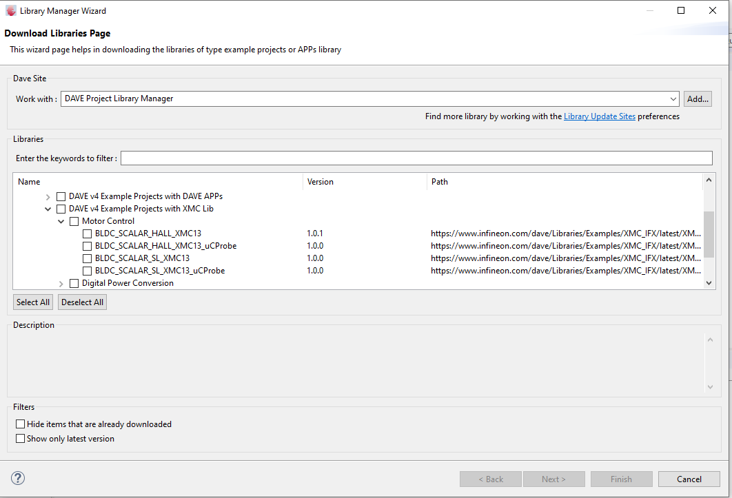
Presently am working on 2 examples given by Infineon (below is the image) one is 'BLDC_SCALAR_HALL_XMC13' and 'BLDC_SCALAR_SL_XMC13' and our custom motor was designed for 120 Commutation or phase shift.
1) BLDC_SCALAR_HALL_XMC13
I have tested our custom motor (3KW) with these example project 'BLDC_SCALAR_HALL_XMC13' with HALL sensors and it is working.
As observed from DSO, we are getting trapezoidal voltage and current waveforms, but all we need is sinusoidal control, How can we achieve with above example and what are the changes to be done in SW ?
2) BLDC_SCALAR_SL_XMC13
I have tested 120W motor with these example project 'BLDC_SCALAR_SL_XMC13' and run the motor without HALL sensor and it is working
As you suggested: For sinusoidal control, you may refer to the sensorless FOC algorithm.
a) Is BLDC_SCALAR_SL_XMC13 what you recommend for sensorless FOC ?
b) Can we achieve sinusoidal control mechanism (voltage and current ) with these example ?
c) Is it possible to change Commutation (120 or 180) mode in SW ?
can you please give me clarity to proceed further ..
Thanking you
Suraj,N
- Mark as New
- Bookmark
- Subscribe
- Mute
- Subscribe to RSS Feed
- Permalink
- Report Inappropriate Content
Hello Suraj
The following link should have PMSM_FOC_EXAMPLE which should be able to generate sinusoidal voltages:
https://www.infineon.com/cms/en/product/promopages/aim-mc/dave_downloads.html
Please go through the example project to understand how the algorithm functions.
Is there any particular reason why you would want to modify your existing code? It would be much simpler to use the above example project.
If you need further help, please let me know.
Regards
- Mark as New
- Bookmark
- Subscribe
- Mute
- Subscribe to RSS Feed
- Permalink
- Report Inappropriate Content
Hi RupakC,
Thanks for the reply
I have gone through the PMSM_FOC_EXAMPLE code, the configuration was done through APP and code generated.
1) Can we use above example code and run our custom BLDC motor using Controller card: KIT_XMC1300_DC_V1 for sinusoidal control?
1.1) If yes, can you please tell me the above PMSM_FOC_EXAMPLE code can be used for both Sensored (HALL sensor) and Sensorless (without HALL sensor) control ?
1.2) What is the difference from BLDC_SCALAR_HALL_XMC13, BLDC_SCALAR_SL_XMC13 to PMSM_FOC_EXAMPLE.
Only Trapezoidal and Sinusoidal Control Mechanism ?
Please provide me with necessary solutions for above queries
Thanking you sir,
Suraj, N
- Mark as New
- Bookmark
- Subscribe
- Mute
- Subscribe to RSS Feed
- Permalink
- Report Inappropriate Content
Hello @Suraj
1. Yes. You may use the example code and run your custom BLDC motor using KIT_XMC1300_DC_V1 for sinusoidal control
2. PMSM_FOC_EXAMPLE code can be used only for Sensorless control. It does not support HALL sensors. You need to write your custom code for implementing sensored FOC control.
3. The control algorithm for trapezoidal control and FOC is entirely different. The two are independent algorithms. Please refer to the documentation within the respective zipped folder (you will have this once you download the example project) to know more about the differences in the algorithms.
Regards
- Mark as New
- Bookmark
- Subscribe
- Mute
- Subscribe to RSS Feed
- Permalink
- Report Inappropriate Content
Hello RupakC,
Thanks a lot
Am presently testing 'PMSM_FOC_SL_XMC13_PUBBLIC_V1_5_8_LIB' example by configuring 120W motor with KIT_XMC1300_DC_V1 Control Card and DEMO-PTOOL-300W-M Power card. but am unable to run the motor
Configurations:
1) MCUCARD_TYPE == KIT_XMC1300_DC_V1
2) INVERTERCARD_TYPE == CUSTOM_INVERTER
3) MOTOR_TYPE == CUSTOM_MOTOR
4) MY_FOC_CONTROL_SCHEME = SPEED_CONTROLLED_VF_MET_FOC (also tried with SPEED_CONTROLLED_DIRECT_FOC)
5) CURRENT_SENSING = USER_SINGLE_SHUNT_CONV
As I Configured all PWM, ADC and Inverter pins according to XMC1300 MCU and for current sensing am using single shunt as feedback for position detection and 3-shunt current feedback is not possible with KIT_XMC1300_DC_V1 (Control Card) & DEMO-PTOOL-300W-M (Power card), because xmc1300 have given Phase voltages to monitor in HW and Phase currents are not provided, and DC shunt current is mainly used for overcurrent protection so what is the startup algorithm initially used to detect and run the motor. Can you explain me in detail ?
Thanking you
Suraj,N