

- Mark as New
- Bookmark
- Subscribe
- Mute
- Subscribe to RSS Feed
- Permalink
- Report Inappropriate Content
Hi,
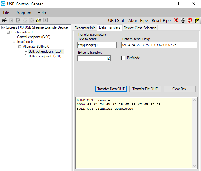
I have to transfer data from FX3 to FPGA using GPIF II interface.I'm using the firmware that is in AN65974 and i will give data through control center.But i'm able to receive only starting 2 bytes,the remaining bytes are missing,as shown in below snapshot.What may be the reason for this,kindly anyone let me know the issue.

Regards,
Aswini
Solved! Go to Solution.
- Mark as New
- Bookmark
- Subscribe
- Mute
- Subscribe to RSS Feed
- Permalink
- Report Inappropriate Content
Hello Aswini,
I tried to reproduce at my end.
I programmed the FX3 with default firmware and checked the flags before and after transfer (without reading it on GPIF side)

These are the traces i got with proper PCLK - initially low and gets high when some data is transferred. Flags C goes low again when DMA buffer is FULL

I also observed that if PCLK is not given properly these flags misbehave. Trace with flags without proper PCLK and before data transfer .

Initially before transfer both flags will be low as mentioned in state machine. So before transferring you should get both flags low.

Regards,
Rashi
Rashi

- Mark as New
- Bookmark
- Subscribe
- Mute
- Subscribe to RSS Feed
- Permalink
- Report Inappropriate Content
Hello Aswini,
Can you probe the PCLK line, for reference, to know the number of bytes read.
Also let me know, you have programmed the FX3 for which transfers: Stream_IN_OUT or SF_shrt_ZLP?
Can you program the FX3 with the .img file attached and keep the data size as a multiple of 1024 in USB3 or 512 in USB2. Probe the lines at GPIF interface and share the results.
Regards,
Rashi
Rashi
- Mark as New
- Bookmark
- Subscribe
- Mute
- Subscribe to RSS Feed
- Permalink
- Report Inappropriate Content
- Mark as New
- Bookmark
- Subscribe
- Mute
- Subscribe to RSS Feed
- Permalink
- Report Inappropriate Content
Hello Aswini,
Please let us know are you programming the FPGA with .bit file which is given with AN65974 application note.
If yes, the .bit file will not support transfers (reading) like 12 bytes, 2 bytes that you are trying. The .bit file supports full packet transfers as mentioned table 6 under section 11.5.1.
You have to develop customize FPGA .bit file for reading transfers like this.
Regards,
Rashi
Rashi
- Mark as New
- Bookmark
- Subscribe
- Mute
- Subscribe to RSS Feed
- Permalink
- Report Inappropriate Content
Hello,
Please let us know are you programming the FPGA with .bit file which is given with AN65974 application note.
I'm using different bit file (zynq FPGA).
Regards,
Aswini
- Mark as New
- Bookmark
- Subscribe
- Mute
- Subscribe to RSS Feed
- Permalink
- Report Inappropriate Content
Hello Aswini,
The FPGA programming (.bit file in the folder with AN 65974) is done such that the FPGA can only read full packets (1024 bytes - USB 3.0 and 512 bytes - USB 2.0).
You need to develop your own FPGA code (.bit file) to short packets.
Also ,the FPGA state machine switched to read mode only when the status of the switches are as mentioned below. If your FPGA (ZYNC) board will not have switches at same positions, hence the read mode cannot be selected in such case.

So you need to develop your customized FPGA bit file
Regards,
Rashi
Rashi
- Mark as New
- Bookmark
- Subscribe
- Mute
- Subscribe to RSS Feed
- Permalink
- Report Inappropriate Content
Hi,
I have developed custom bit file and set the FPGA transfer mode as Stream Bulk OUT ,so we are getting first 2bytes from fx3 to fpga.
I cannot probe pclk from fpga as it was showing some error in fpga side.
What may be the reason for not getting the remaining bytes.please let me know.
Regards,
Aswini
- Mark as New
- Bookmark
- Subscribe
- Mute
- Subscribe to RSS Feed
- Permalink
- Report Inappropriate Content
Hello Aswini,
We need to know the for how many clock cycles does the SLRD is pulled low. Without clock cycles it is difficult to say the reason for the problem. There is a possibility that 2 bytes of data is read because the SLRD is not pulled low for enough time.
Because the time period SLRD will be pulled low, the data can be read by the FPGA from the GPIF line. It would be good to get the PCLK traces.
As per the traces shared in the response 17 of the thread Data from FX3 to FPGA is repeating continuously SLRD is not going low.
If you say 2 bytes are read, SLRD should be asserted Low for that
Condition to be met for data read
SLWR : High
SLRD : Low;
SLCS: Low
SLOE : Low
PKTEND: High
Please share the traces with PCLK and the above GPIF interface lines meeting above mentioned conditions .
Regards,
Rashi
Rashi
- Mark as New
- Bookmark
- Subscribe
- Mute
- Subscribe to RSS Feed
- Permalink
- Report Inappropriate Content
- Mark as New
- Bookmark
- Subscribe
- Mute
- Subscribe to RSS Feed
- Permalink
- Report Inappropriate Content
Hello Aswini,
Thanks you for the traces.
Please let me know the time for which SLRD is asserted low.
Also confirm that these traces are taken when FX3 is programmed with the firmware shared in response 16 of this thread Data from FX3 to FPGA is repeating continuously
As per the default state machine (GPIF II), data is driven to GPIF II lines till the time SLRD is low. As soon as SLRD the goes high the data won't be driven.
From the traces you shared flag c is LOW every time (which means buffer is empty). Please confirm there are no modifiactions done with flag c polarity. Flag C should be high at first as soon as you read the data from the DMA buffer it should go low (which shows the buffer is empty). On reading the Flga c the FPGA should assert SLRD high (which means stop reading from that socket/buffer).
Regards,
Rashi
Rashi
- Mark as New
- Bookmark
- Subscribe
- Mute
- Subscribe to RSS Feed
- Permalink
- Report Inappropriate Content
Hello,
The SLRD signal is getting triggered as shown in below snapshot ,but i'm receiving only 2 bytes of data when SLRD is low.I'm using the default firmware with that i just modified GPIF II interface(state machine and polarity of flags as active high),in FPGA(Zynq) side i'm using customized bit file not the one in AN65974.With the default firmware i'm getting FFFF so i made these changes.

The state machine which i have modified is below,

kindly let me know the solution for this issue.
Regards,
Aswini
- Mark as New
- Bookmark
- Subscribe
- Mute
- Subscribe to RSS Feed
- Permalink
- Report Inappropriate Content
Hello,
I have one more doubt , through Control center i have sent some bytes and in FPGA side i'm receving 2 bytes .if i sent the another data again through control center i'm able to receive 4 bytes in FPGA side(previous data 2 bytes and present data 2 bytes) as shown below,

What may the reason for this?
Regards,
Aswini
- Mark as New
- Bookmark
- Subscribe
- Mute
- Subscribe to RSS Feed
- Permalink
- Report Inappropriate Content
Hello Aswini,
For this you can check the DMA buffer contents.
When you get the PROD event (i.e. received the data from USB) you can call the CyU3PDmaMultiChannelGetBuffer (in the DMA call back)and store contents of Dma buffer and later get that buffer value printed. So that we can know what exactly is in the buffer and what is the FPGA reading.
Regards,
Rashi
Rashi
- Mark as New
- Bookmark
- Subscribe
- Mute
- Subscribe to RSS Feed
- Permalink
- Report Inappropriate Content
Hello,
Here is a snippet i used to check no.of buffers get transmitted,i have checked this before using microsoft visual studio the txcount got incremented but with that (microsoft visual studio) there is some issue.
if( type == CY_U3P_DMA_CB_CONS_EVENT)
{
rxcount++;
}
if( type == CY_U3P_DMA_CB_PROD_EVENT)
{
txcount++;
}
So,can you tell me another solution to solve this problem.
Regards,
Aswini
- Mark as New
- Bookmark
- Subscribe
- Mute
- Subscribe to RSS Feed
- Permalink
- Report Inappropriate Content
Hello Aswini,
I am not sure why do you use Microsoft Visual Studio. You can used UART debug prints to print the content (or first two bytes) of DMA buffer and not the how many times the PROD events occur.
Did you get the rxcount?
Please confirm that UART block is enabled in your firmware. If yes you can use UART for debug purpose. Print the values of these variable or get the DMA buffer contents and print the value.
If not, get the DMA buffer contents using CyU3PDmaMultiChannelGetBuffer and you can send this buffer (to USB) using a vendor command. When you send the vendor command you will receive the DMA buffer contents.
Regards,
Rashi
Rashi
- Mark as New
- Bookmark
- Subscribe
- Mute
- Subscribe to RSS Feed
- Permalink
- Report Inappropriate Content
Hello,
Yes,the UART block is enabled in the firmware.I didin't tried to check debug prints before,now i will try and let you know the result.
And also let me know whether UART should be enabled in GPIF II intrface settings.
Regards,
Aswini
- Mark as New
- Bookmark
- Subscribe
- Mute
- Subscribe to RSS Feed
- Permalink
- Report Inappropriate Content
Hello Aswini,
Please confirm which part number are you using in the design. You can refer to the respective datasheet (pin description section) and check the GPIF configuration that you are suing supports UART or not and at which pins
Regards,
Rashi
Rashi
- Mark as New
- Bookmark
- Subscribe
- Mute
- Subscribe to RSS Feed
- Permalink
- Report Inappropriate Content
Hello,
The Words from your previous reply "check the GPIF configuration that you are suing supports UART or not" .How can i check it?
Did you mean i/o configuration,
io_cfg.useUart = CyTrue;
io_cfg.useI2C = CyFalse;
io_cfg.useI2S = CyFalse;
io_cfg.useSpi = CyFalse;
If not please let me know.
Regards,
Aswini
- Mark as New
- Bookmark
- Subscribe
- Mute
- Subscribe to RSS Feed
- Permalink
- Report Inappropriate Content
Hello Aswini,
As per the discussion of GPIF thread. It seems there is some problem in the FPGA > GPIF interface.
To check whether the interface we would need the traces of the interfacing signals using external analyzer (oscilloscope). Please provide us the traces.
Regards,
Rashi
Rashi
- Mark as New
- Bookmark
- Subscribe
- Mute
- Subscribe to RSS Feed
- Permalink
- Report Inappropriate Content
Hello,
Yeah,we are still working on that and we will send you the traces as soon as possible.
Regards,
Aswini
- Mark as New
- Bookmark
- Subscribe
- Mute
- Subscribe to RSS Feed
- Permalink
- Report Inappropriate Content
Hello,
Can you tell me how you used to check debugprints using UART?
I am using Teraterm for the same.
Steps followed:
1.Program Fx3
2.Debug FX3.
3.Connecting COM port in Teraterm and checking for prints.
But I am not getting Debugprints
Regards,
Aswini.
- Mark as New
- Bookmark
- Subscribe
- Mute
- Subscribe to RSS Feed
- Permalink
- Report Inappropriate Content
Hello Aswini,
Please let me know which pins are you suing for UART.
As per the FX3S part, when storage port 0 is enabled, port 1 is disabled an and lpp mode is default
CyU3PMemSet ((uint8_t *)&io_cfg, 0, sizeof (io_cfg));
io_cfg.isDQ32Bit = CyFalse;
io_cfg.useUart = CyTrue;
io_cfg.useI2C = CyFalse;
io_cfg.useI2S = CyFalse;
io_cfg.useSpi = CyFalse;
io_cfg.lppMode = CY_U3P_IO_MATRIX_LPP_DEFAULT;
io_cfg.s0Mode = CY_U3P_SPORT_8BIT;
io_cfg.s1Mode = CY_U3P_SPORT_INACTIVE;
/* No GPIOs are enabled. */
io_cfg.gpioSimpleEn[0] = 0;
io_cfg.gpioSimpleEn[1] = 0;
io_cfg.gpioComplexEn[0] = 0;
io_cfg.gpioComplexEn[1] = 0;
status = CyU3PDeviceConfigureIOMatrix (&io_cfg);
if (status != CY_U3P_SUCCESS)
{
goto handle_fatal_error;
}
For 16 bit configuration and lpp mode default only
Pins[46]-[49] are UART pins

FX3S datasheet
Similarly, if you are working with FX3 (CYUSB301x) you need to refer FX3 datasheet
Please let me know if any queries
Regards,
Rashi
Rashi
- Mark as New
- Bookmark
- Subscribe
- Mute
- Subscribe to RSS Feed
- Permalink
- Report Inappropriate Content
Hello,
Based on the above snippet i have modified in my firmware.
For 16 bit configuration and lpp mode default only
Pins[46]-[49] are UART pins
I'm using the same.
After all these changes i'm getting some garbage data in Tera term as shown in below snapshot.
Then why I'm getting these garbage data, somewhere i'm missing.Kindly let me know.
Regards,
Aswini
- Mark as New
- Bookmark
- Subscribe
- Mute
- Subscribe to RSS Feed
- Permalink
- Report Inappropriate Content
Hello,
Based on your previous reply "We need to know the for how many clock cycles does the SLRD is pulled low. Without clock cycles it is difficult to say the reason for the problem. There is a possibility that 2 bytes of data is read".
I'm trying to probe the clock but i'm getting the below errors.

When i check the clock using Picoscope i got the below output.

Clock is generating as shown above ,but we can't able to display the clock with other signals in ila probes.
Regards,
Aswini
- Mark as New
- Bookmark
- Subscribe
- Mute
- Subscribe to RSS Feed
- Permalink
- Report Inappropriate Content
Hello Aswini,
As you can probe the clock trace. Please let me know the clock frequency as well as time period for which SLRD is low (reading)
Regards,
Rashi
Rashi
- Mark as New
- Bookmark
- Subscribe
- Mute
- Subscribe to RSS Feed
- Permalink
- Report Inappropriate Content
Hello,
We are using 54Mhz from FPGA side,SLRD is going low (which is needed for data transfer).But SLRD is going low for 2 times out of 4096 samples,it is getting low only 2 times each of duration 1 sample as attached below.When SLRD went low,I am getting 0x00 and when it is high I am getting FF.
I am using AN65974 firmware and GPIF II SM without any changes,I am getting below output.

When I am changing actions in AN65974 SM,I am getting 2 bytes.Without modifications,I am getting only 00 when SLRD is low.
As you told to probe the clock and check SLRD signal,we tried for the same and we are unable to get the clock signal.So,please tell us by assuming that it is going low only during that time and what will be solution for this?
Regards,
Aswini.
- Mark as New
- Bookmark
- Subscribe
- Mute
- Subscribe to RSS Feed
- Permalink
- Report Inappropriate Content
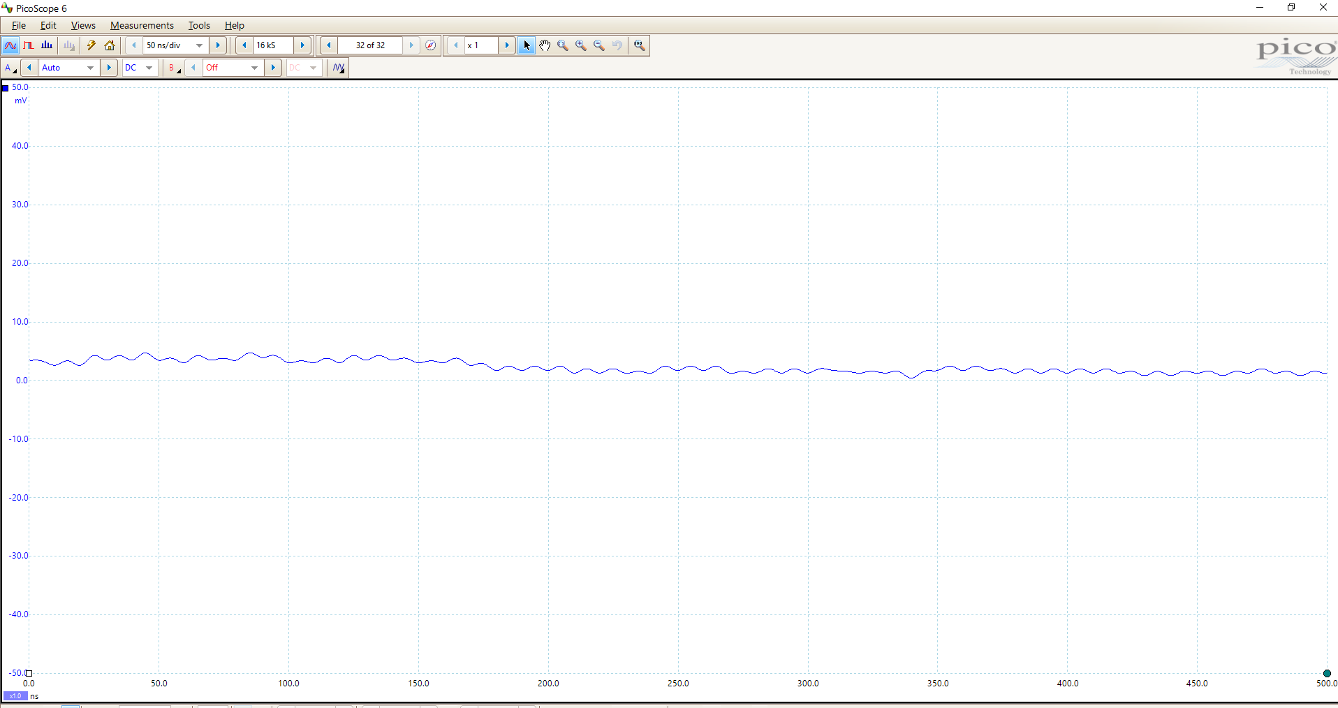
Hello,
I have checked the clock using oscilloscope and the frequency of clock is 54 Mhz as shown in below snapshot.

Regards,
Aswini
- Mark as New
- Bookmark
- Subscribe
- Mute
- Subscribe to RSS Feed
- Permalink
- Report Inappropriate Content
Hello Aswini,
Thank you for the traces. The clock signals from the FPGA are not uniform all over. It would be better if you can improve the clock out signal.
- As there is confusion for the state of the DMA flags. Please confirm that the flags sampled by the FPGA as active high or active low.
- Also probe the SLRD line and let me the time period for which it is low using oscilloscope (i.e. the data is being read) when you transfer 1024 bytes of data.
- Please share the oscilloscope traces for FLAGS, along with the SLRD.
Regards,
Rashi
Rashi
- Mark as New
- Bookmark
- Subscribe
- Mute
- Subscribe to RSS Feed
- Permalink
- Report Inappropriate Content
Hello,
Please confirm that the flags sampled by the FPGA as active high or active low.
I'm using the default firmware without any modifications,and flags are active low.
Another thing is consumer event is generating if i send 12 bytes of data,if i send 1024 bytes consumer event is not generated.
Regards,
Aswini
- Mark as New
- Bookmark
- Subscribe
- Mute
- Subscribe to RSS Feed
- Permalink
- Report Inappropriate Content
Hello Aswini,
The traces you shared are not clear. I am not able to see the time for which SLRD is low. Please share proper traces for faster debugging of the issue.
I am not sure how is this working. I would need proper traces for the debug
Regards,
Rashi
Rashi
- Mark as New
- Bookmark
- Subscribe
- Mute
- Subscribe to RSS Feed
- Permalink
- Report Inappropriate Content
- Mark as New
- Bookmark
- Subscribe
- Mute
- Subscribe to RSS Feed
- Permalink
- Report Inappropriate Content
Hello Aswini,
As per our discussion, there is some problem in FPGA implementation i.e. SLRD is not asserted low for expected time period
So after modifying the FPGA implementation we can debug the problem (if any)
Regards,
Rashi
Rashi
- Mark as New
- Bookmark
- Subscribe
- Mute
- Subscribe to RSS Feed
- Permalink
- Report Inappropriate Content
Hello,
I am working on that,i will let you know the result.
Regards,
Aswini.
- Mark as New
- Bookmark
- Subscribe
- Mute
- Subscribe to RSS Feed
- Permalink
- Report Inappropriate Content
Hello,
Here i'm using Default firmware and GPIF Interface.
Based on your suggestions,I have modified FPGA Implementation,by using current_stream_out_state i came to know in which mode FPGA is stopped.
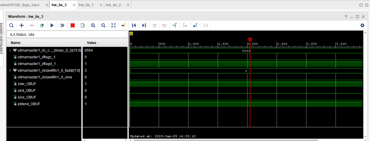
The result of Current_stream_out and flags are shown below.


Below snippet explains the flagd condition,

Here to get into stream_out_read mode,the flagd should be 1,but here the flagd is 0.So,it remains in stream_out_wait_flagd state.
Flags are output of FX3,let me know what can be done to get flagd as 1.
Regards,
Aswini
- Mark as New
- Bookmark
- Subscribe
- Mute
- Subscribe to RSS Feed
- Permalink
- Report Inappropriate Content
Hello Aswini,
Please let me know the traces you shared are after or before sending data.
Please try to send 512 bytes of data and then take the traces. Is the flag d always low or is it high before transferring data?
Regards,
Rashi
Rashi
- Mark as New
- Bookmark
- Subscribe
- Mute
- Subscribe to RSS Feed
- Permalink
- Report Inappropriate Content
Hello,
Please let me know the traces you shared are after or before sending data.
The traces are after sending data,and i have sent 16384 bytes.
Please try to send 512 bytes of data and then take the traces.
If I try to send 512 bytes,before and after data transfer values are same there is no change as below.


And for 16384 bytes,the initial values are as shown below.


After sending data the result was sent in previous reply.
But,In slfifosync.h file by making DMA_BUF_SIZE as 512,
then inital current_stream_out=0,flagd=1
after sending data,current_stream_out=2,flagd=0
I'm able to send the no.of bytes=DMA_BUF_SIZE.
Regards,
Aswini
- Mark as New
- Bookmark
- Subscribe
- Mute
- Subscribe to RSS Feed
- Permalink
- Report Inappropriate Content
Hello Aswini,
If the flag d = 1; the current state is not going to 3 i.e reading the data.
In the traces i can see the flag d =1 and current state still at 0.
- please send the data equal to the DMA buffer size and read the current state output.
- The initial value of these DMA flags i.e. (before transferring data) is LOW. But from the traces it doesn't seem so please confirm the connections of the flags to FPGA are proper
- Please keep the default firmware as it is. Don't modify the firmware as this will create more confusion. We can work with the default firmware and later make the changes if needed.
Regards,
Rashi
Rashi
- Mark as New
- Bookmark
- Subscribe
- Mute
- Subscribe to RSS Feed
- Permalink
- Report Inappropriate Content
Hello,
In FPGA side,I'm using the same FPGA files that is in AN65974,but there they are using fdata as inout port because it's loopback transfer.
So I made fdata as input and output(fdata_in and fdata_out)and replaced in the respective places.With that the result i have sent you in the above replies.
So,with only one change (fdata inout as fdata output),I created IP and checked the result,the result is flagc,flagd and current_streamout_mode is 0 always.
I'm looking over the FPGA files now,by seeing all this if you get any idea regarding this let me know.
Regards,
Aswini
- Mark as New
- Bookmark
- Subscribe
- Mute
- Subscribe to RSS Feed
- Permalink
- Report Inappropriate Content
Hello Aswini,
Can you probe Flag C and Flag D lines using oscilloscope for both situation i.e. before and after transferring data.
Regards,
Rashi
Rashi
- Mark as New
- Bookmark
- Subscribe
- Mute
- Subscribe to RSS Feed
- Permalink
- Report Inappropriate Content