

- Mark as New
- Bookmark
- Subscribe
- Mute
- Subscribe to RSS Feed
- Permalink
- Report Inappropriate Content
Hello,
I am experimented the FX3 development board and an OV7670 camera, i was able to alter the AN75779 project based on the UVC and FX3 documentation. Now i have a custom UVC board with an FX3 IC, based on the experiences with the OV7670 I made some modifications:
- GPIF
- data bus 8bit->16bit
- LD_ADDR_COUNT: change to 8183
- LD_DATA_COUNT: change to 8183
- cyfxuvcdscr.c file
- width and height modified to 400*400
- Format changed YUY2 to MJPEG
- Changed bit rates, fps to 30 fps
- uvc.c
- changed the I2C address for configuring the sensor
- Changed the pwm for generating clk for the image sensor
Now I only capturing black frames, i checked the the clock signal and read out some register values via i2c, also checked the device in wireshark, and USB device viewer. Device is enumerating as a UVC device descriptors are OK, generating the clock signal, i2c communication works well, and the wireshark says the UVC requests works well.
But I all i got is black screen. I would appreciate any kind of help, try to find out the problem about 2 weeks.
Best regards
Solved! Go to Solution.
- Labels:
-
USB Superspeed Peripherals
- Mark as New
- Bookmark
- Subscribe
- Mute
- Subscribe to RSS Feed
- Permalink
- Report Inappropriate Content
Hello Bence,
I apologize for missing out one important thing in my debug.
I just went through the project once again. I found that the GPIF II Designer project was not modified based on the description given in your first interaction i:e:
- GPIF
- data bus 8bit->16bit
- LD_ADDR_COUNT: change to 8183
- LD_DATA_COUNT: change to 8183
To confirm if my understanding is proper or not, I checked the registers inside the file cyfxgpif2config.h. I found that the value of the register defined by the comment CY_U3P_PIB_GPIF_BUS_CONFIG is set to 0x00000003. This value is used for the configuration of the register GPIF_BUS_CONFIG. You can refer to the FX3 TRM to understand the different fields of the GPIF_BUS_CONFIG register. So, by comparing the value set with the register fields, I understood that you are still making use of an 8 bit interface and not 16 bit interface.
Please correct me if my understanding is wrong. If my understanding is correct, then you will be sampling only 1 byte of data at each PCLK instead of 2 bytes of data that is actually required. This could be the reason for the frame size to be halved at the PC side.
Please try building the GPIF II state machine by modifying the bus width and counter limit again. After this, please include the latest header file generated in the project so that the change in the data bus width and counters are reflected in the project.
Please let me know if you have any queries on this.
Jayakrishna
- Mark as New
- Bookmark
- Subscribe
- Mute
- Subscribe to RSS Feed
- Permalink
- Report Inappropriate Content
Hello,
The black screen is usually seen when the frame size received at the host side is not same as the frame size transmitted by FX3 or when there are any failures in video transfer. Please ensure that the sensor is configured properly for the required resolution and frame rate.
Also, please share the following so that we can debug this issue faster:
1. UART debug logs
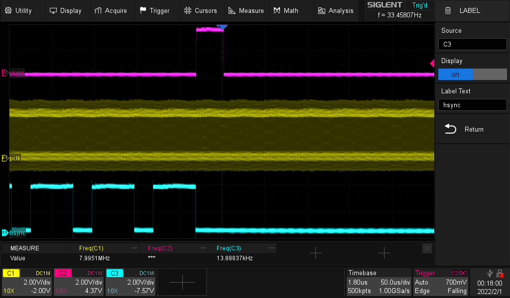
2. Snapshot of HSYNC, VSYNC and PCLK traces. This is to ensure that the data is consistent and is received by the FX3 device.
In addition to this, please let us know on which host application the tests were done? Is it on MPC-HC? If not, then can you please try using MPC-HC or Windows in box camera application to test video streaming?
Jayakrishna

- Mark as New
- Bookmark
- Subscribe
- Mute
- Subscribe to RSS Feed
- Permalink
- Report Inappropriate Content
Sorry for the slow response, but we are using a custom pcb with an FX3 ic so we needed time to interface the asked traces(also we do not have UART debug log). I will attach the pictures from our scope. We generating a 24 MHz clock signal for the OV426 IC and at the FX3 side we checked the PCLK 8MHz signal and VSYNC 33 Hz HSYNC 14 kHz. So we have all the signals but still got black screen. I already read the trouble shooting guide, but did not get closer to the solution. I attached the project and pictures about the traces. Currently I try to investigate the situation with wireshark.
Best Regards,
Bence
- Mark as New
- Bookmark
- Subscribe
- Mute
- Subscribe to RSS Feed
- Permalink
- Report Inappropriate Content
Hello Bence,
As mentioned in the following KBA, for synchronous interfaces, the supported clock frequency is in between 10MHz and 100MHz:
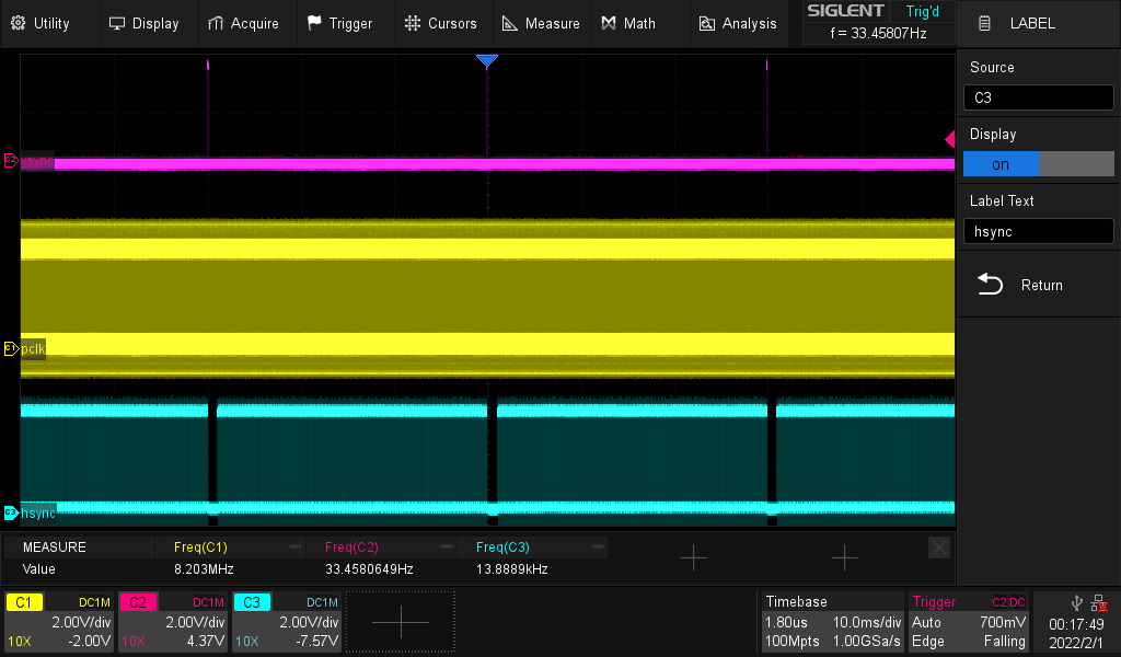
I find that you are using 8MHz as the interface clock in your configuration which is not supported. So, please increase the interface clock frequency above 10MHz.
Also, please share the Wireshark traces for us to review.
Jayakrishna
- Mark as New
- Bookmark
- Subscribe
- Mute
- Subscribe to RSS Feed
- Permalink
- Report Inappropriate Content
First of all thank you for your fast response. We increased the pclk over 10MHz(scope picture attached). Still got only black screens. Currently we are capturing the USb traffic via USBTrace(picture also attached). In my opinion we have Href Vref pclk but still not get frames.
Best Regards,
Bence


- Mark as New
- Bookmark
- Subscribe
- Mute
- Subscribe to RSS Feed
- Permalink
- Report Inappropriate Content
Hello,
Please share the Wireshark traces for us to debug the issue.
Jayakrishna
- Mark as New
- Bookmark
- Subscribe
- Mute
- Subscribe to RSS Feed
- Permalink
- Report Inappropriate Content
- Mark as New
- Bookmark
- Subscribe
- Mute
- Subscribe to RSS Feed
- Permalink
- Report Inappropriate Content
Hello Bence,
It looks like FX3 device is not sending any data to the USB host from the traces shared. We need to have the debug logs captured to understand what exactly fails within the firmware. Please refer to the following blog post and add a CDC interface to your project so that we can get the debug logs:
Even though the above blog post is written for Slave fifo example, you can use it as a reference to add CDC interface to your project and to obtain the debug logs. Please share the debug logs for us to debug the issue.
Jayakrishna
- Mark as New
- Bookmark
- Subscribe
- Mute
- Subscribe to RSS Feed
- Permalink
- Report Inappropriate Content
Hello Jayakrishna,
We not implemented the CDC yet, but we were able to send frames to the PC, but now we got 30 fps black screens. We already checked that the sensor is fully operational. Also we were able to catch the USBtrace(attached).
Do you have any suggestion where should we search for the solution?
Best Regards,
Bence
- Mark as New
- Bookmark
- Subscribe
- Mute
- Subscribe to RSS Feed
- Permalink
- Report Inappropriate Content
Hello Bence,
How did you confirm that you are receiving "30fps black screen"? Please share the full Wireshark traces for us to review. We suspect that the sensor is only sending frames having size equal to half of that reported in the descriptors.
It will be also good if we can have the debug logs too using CDC interface.
Jayakrishna
- Mark as New
- Bookmark
- Subscribe
- Mute
- Subscribe to RSS Feed
- Permalink
- Report Inappropriate Content
Hello Jayakrishna,
We testing the the camera with AMCap application and an OpenCV based self developed C++ application and both of them said they got 30-33 fps 400*400 pixel images. I attached the USB tarce from wireshark, and currently working on the CDC interface. For the raw 10 bit RGB image we are using MJPEG Frame Type Descriptor is it the proper format for this type of image? Where did you catched the half sized frames in the trace?
Best Regards,
Bence
- Mark as New
- Bookmark
- Subscribe
- Mute
- Subscribe to RSS Feed
- Permalink
- Report Inappropriate Content
Hello Bence,
Please refer to the following snapshot from your trace:

As you might be knowing, the frame should end with a partial buffer. So, here 12727 bytes refer to the last partial buffer that shows the end of a frame. The others are all full buffers (16407 bytes) are all full buffers.
From the trace, there are 9 full buffers followed by one partial buffer. Wireshark adds 27 bytes header to the captured data. Also, FX3 firmware adds 12 bytes of UVC header to each DMA buffer committed to the host.
So, the actual size of a full buffer = 16407 - 27 - 12 = 16368 bytes
The size of a partial buffer = 12727 - 12 - 27 = 12688 bytes
Therefore, total size of frame = 9 x 16368 + 12688 = 1,60,000 bytes
From your descriptors, the frame size expected is 3,20,000 bytes
So, I feel that the sensor is sending less data than the actual frame size required.
RAW10 is not supported by UVC. You can refer to the following KBA to understand how to stream RAW10 data as YUY2:
Even though the above KBA is for CX3 (CYUSB306x), you can use it as a reference for FX3 descriptors too. The above KBA has got some example descriptors. You can refer to Example 1 section of the above KBA as it is more relevant to FX3.
Jayakrishna
- Mark as New
- Bookmark
- Subscribe
- Mute
- Subscribe to RSS Feed
- Permalink
- Report Inappropriate Content
Hello Jayakrishna,
We have started to implement the CDC part for debugging the board. We have a working firmware for a different camera module (OV7670). And we started to alter the code based on the KBA229099 and the USBVideoClassBulk_USBUart example code. If we adding the CDC part of the code, the enumeration process always fails. Modified the configuration descriptor based on the KBA instructions and the example code. I am sure we are missing the point somewhere, but run out of ideas where.
Please can you check the descriptor part we are using?(without the CDC part it works properly)
Best Regards,
Bence
- Mark as New
- Bookmark
- Subscribe
- Mute
- Subscribe to RSS Feed
- Permalink
- Report Inappropriate Content
Hello,
Can you please share the complete project for us to understand the code better. We need to understand the #defines used in the code. For ex: In the descriptors, USB_DEBUG_INTERFACE is used to enable the vendor interface. But, we are not sure if this is enabled or disabled. So, kindly share this so that we can understand the problem better.
You can also refer to the following thread where CDC interface was enabled on CX3 firmware:
https://community.infineon.com/t5/USB-superspeed-peripherals/Add-CDC-device-to-CX3/m-p/275828
Even though CX3 firmware is different when we compare with FX3 firmware, you can use it as a reference for modifying the descriptors. Please try this and let me know if you still face any issues.
Jayakrishna
- Mark as New
- Bookmark
- Subscribe
- Mute
- Subscribe to RSS Feed
- Permalink
- Report Inappropriate Content
Hello,
I started to investigate the thread you mentioned. Thank you for your help. Without the CDC part (at the super seed descriptors) and the modified dexriptor length and interface number the firmware works properly.
Best Regards,
Bence
- Mark as New
- Bookmark
- Subscribe
- Mute
- Subscribe to RSS Feed
- Permalink
- Report Inappropriate Content
Hello,
Please find the attachment in which the default project from AN75779 is modified to add CDC interface and vendor interface. You can use it as a reference for adding CDC interface to your projects.
I have also modified your project and tested it at my end. It enumerates fine at my end. Please check by referring to the attached project.
Jayakrishna
- Mark as New
- Bookmark
- Subscribe
- Mute
- Subscribe to RSS Feed
- Permalink
- Report Inappropriate Content
Hello,
I have to find the attachement in your previous response(which misses it), or in an older response?
Best Regards,
Bence
- Mark as New
- Bookmark
- Subscribe
- Mute
- Subscribe to RSS Feed
- Permalink
- Report Inappropriate Content
Hello Bence,
I have edited my previous reply (just previous) and attached the projects along with it. Please let me know if you are still not able to find the attachment.
Jayakrishna
- Mark as New
- Bookmark
- Subscribe
- Mute
- Subscribe to RSS Feed
- Permalink
- Report Inappropriate Content
Thank you for your response. The enumeration works fine. I tried to modify the uvc.c code based on the cyfxusbdebug example project to use the debugprint function to show messages, but the only thing i got is the the device not shown in the device manager, not enumerate. Not really understand what happening.
Is there a short cut to use the CyU3PDebugPrint function to show debug messages via USB.
- Mark as New
- Bookmark
- Subscribe
- Mute
- Subscribe to RSS Feed
- Permalink
- Report Inappropriate Content
Hello,
Please refer to the following KBA:
Jayakrishna
- Mark as New
- Bookmark
- Subscribe
- Mute
- Subscribe to RSS Feed
- Permalink
- Report Inappropriate Content
Hello,
we were able to modify the project based on the KBA231478 and got the debug prints from the FX3 development board, but our custom board is only capable high speed, so i started to modify the high speed descriptors based on the super speed descriptors but the board failed durin enumeration or completly missing in the device manager.
- Mark as New
- Bookmark
- Subscribe
- Mute
- Subscribe to RSS Feed
- Permalink
- Report Inappropriate Content
Hello,
Please check the High Speed configuration descriptors in the project. You can use the modified superspeed descriptors as a reference for this.
Jayakrishna
- Mark as New
- Bookmark
- Subscribe
- Mute
- Subscribe to RSS Feed
- Permalink
- Report Inappropriate Content
Hello,
Thank you based on your descriptors we were able to implement the CDC and debug prints in the original OV426 based project, and we have logs. The logs says it sanding some frame, but not much also the wireshark traces shows not enough data transfer. Based on that informations what can be the sourco of the problem. Not really sure why is more complicated the OV426 data sending than the OV7670.
Best Regards,
Bence


- Mark as New
- Bookmark
- Subscribe
- Mute
- Subscribe to RSS Feed
- Permalink
- Report Inappropriate Content
Hello,
From the traces, it looks like the sensor is still not sending enough data to the FX3 device. Please check the sensor configuration settings again with the sensor vendor.
Jayakrishna
- Mark as New
- Bookmark
- Subscribe
- Mute
- Subscribe to RSS Feed
- Permalink
- Report Inappropriate Content
Hello,
I already contacted the sensor vendor, but until i wait for the response checked the LV FV lines with scope again. I found that the based on the Href lines width and pulse number the sensor sending 400*400 pixel (50us href on time and the complete href times is 28ms which is 400 pulse package ). The FV line shows 30 Hz pulses. Based on that information it looks like the sensor sending enough information, but the DMA buffer or the state machine not respond correctly? uvc.c can contain any part which is responsible for handling correctly a 16 bit bus width High speed device?
Best Regards,
Bence

- Mark as New
- Bookmark
- Subscribe
- Mute
- Subscribe to RSS Feed
- Permalink
- Report Inappropriate Content
Hi Bence,
Did you make any changes in sensor configurations?
Can you please share the UART debug logs and wireshark traces when these lines were captured?
FX3 will sample the data if the sensor sends it properly. I have not found any failures in the UART debug logs too. This is the reason why I suspect that the issue is from the sensor side.
Jayakrishna
- Mark as New
- Bookmark
- Subscribe
- Mute
- Subscribe to RSS Feed
- Permalink
- Report Inappropriate Content

- Mark as New
- Bookmark
- Subscribe
- Mute
- Subscribe to RSS Feed
- Permalink
- Report Inappropriate Content
Hello,
The Wireshark trace still shows lower frame size. Also, the prints are already present in the possible failure points. And as I mentioned before, FX3 is jus a bridge between the sensor and the host. It just transfers the data received from the sensor to the host. So, the issue here should be related to the image sensor.
Jayakrishna
- Mark as New
- Bookmark
- Subscribe
- Mute
- Subscribe to RSS Feed
- Permalink
- Report Inappropriate Content
Please correct me if i wrong. The 30 Hz FV signal means the sensor sending 30 frame but the FX3 has to verify these frames. So from the 30 Hz 400*400 pixel frames only 4-7 frame(lower frame rate) valid frame arrived? Sensor sending 30 frames but they are not valid in some kind of way?
Best Regards,
Bence
- Mark as New
- Bookmark
- Subscribe
- Mute
- Subscribe to RSS Feed
- Permalink
- Report Inappropriate Content
Hello Bence,
Sorry, But I could not understand your previous question. Can you please explain it elaborately?
Jayakrishna
- Mark as New
- Bookmark
- Subscribe
- Mute
- Subscribe to RSS Feed
- Permalink
- Report Inappropriate Content
As you mentioned FX3 is a bridge, it only transfer the data to the PC. The debug prints only shows a low frame rate (4-9fps). But the FV lines which role is to show the end of a frame probed(between sensor and FX3) and they have 30 Hz, it tells me the sensor sending 30frame per sec. But the Pc only got about 7 frame, so the FX3 did not send all the frames. The state machine and the DMA buffer handling is FX3 based, so my question was if the FX3 got 30 frames per sec, but only sending 7 frame to the PC, is there a way that that the sensor sending invalid data, or FX3 could have bad buffer properties which results that most of the frames invalid and not sending them to the PC.
Best Regards,
Bence
- Mark as New
- Bookmark
- Subscribe
- Mute
- Subscribe to RSS Feed
- Permalink
- Report Inappropriate Content
Hello Bence,
Please let me know how exactly did you verify that 7 frames were received at the PC side. Is it by looking into the fps field shown by the host application?
Also, please let us know what is the value of V-Blanking configured for the sensor. We recommend to configure it above 200us while using FX3 SDK 1.3.4.
Jayakrishna
- Mark as New
- Bookmark
- Subscribe
- Mute
- Subscribe to RSS Feed
- Permalink
- Report Inappropriate Content
Hello,
For checking the video stream i am using amcap, virtualdub, vlc and custom opencv application. None of them sensing frame appearing. My arriving frame number estimation is only based on the FX3 debug prints which shows increased frame number and non zero buffers, but yes i could not verify the received frame number. The V/blanking value currently 290us.
Best Regards,
Bence

- Mark as New
- Bookmark
- Subscribe
- Mute
- Subscribe to RSS Feed
- Permalink
- Report Inappropriate Content
Hello Bence,
Please let me know how exactly are you verifying the frame number in firmware.
Also, please confirm that you are using SDK 1.3.4 for testing. If the V-Blanking is greater than 200uS with SDK 1.3.4, then the frames should not be dropped by FX3. In addition to this, I do not find any other failures in the UART debug logs too.
Jayakrishna
- Mark as New
- Bookmark
- Subscribe
- Mute
- Subscribe to RSS Feed
- Permalink
- Report Inappropriate Content
Hello Jayakrishna,
I checked the SDK version, and I am using 1.3.4. And maybe i misunderstood the meaning the debug prints, but i use them for counting frames.

Best Regards,
Bence
- Mark as New
- Bookmark
- Subscribe
- Mute
- Subscribe to RSS Feed
- Permalink
- Report Inappropriate Content
Hi Bence,
The above print just shows the state of GPIF II state machine when the API CyU3PGpifGetSMState() was called. It does not give fps information.
Jayakrishna
- Mark as New
- Bookmark
- Subscribe
- Mute
- Subscribe to RSS Feed
- Permalink
- Report Inappropriate Content
Hi,
In that case i can only rely on the USB traces which shows low data rate(not enough package) and zero frame received in the video applications. And the scope records which shows correct clock signals for HSYNC and VSYNC, but still no image.
Best Regards,
Bence
- Mark as New
- Bookmark
- Subscribe
- Mute
- Subscribe to RSS Feed
- Permalink
- Report Inappropriate Content
Hi Bence,
As mentioned previously in this discussion, the host application expects 3,20,000 bytes of data. But, it just receives half of the data (i.e 1,60,000 bytes). This is the reason for obtaining black screen.
Also, by going through your project and configuration, we don't find any other reason for the drop of data by FX3 device.
Can you please configure the sensor to send a test pattern and read the same data at the host side? After this, can you compare a frame that is transmitted from the sensor with a frame that is received by the host application. This can be used to understand where exactly the data loss occurred.
Another test can be done is mentioned below:
1. Modify the state machine by adding an output GPIO.
2. Toggle this GPIO in the states PUSH_DATA_SCK0 and PUSH_DATA_SCK1
3. Capture a trace containing FV, LV and the output GPIO
4. Count the number of times the GPIO toggled in one FV.
The above test will give the number of pixels sampled by FX3.
Jayakrishna
- Mark as New
- Bookmark
- Subscribe
- Mute
- Subscribe to RSS Feed
- Permalink
- Report Inappropriate Content
I already contacted the vendor of the sensor, but i have to wait for the answer. Also because we are using a custom PCB our electrical engineer colleagues said checking IOs not trivial. Is there a way to make a variable, which can be the counter a GPIF state?
But also something bugging my mind, i kindly ask you to explain me, if the HREF signals length is equals to the 400 pixel(impulse length/pclk=400) and between 2 VSYNC signal I have 400 pcs impulses. Isn't that mean that I have 400 row with 400 pixel. I have clock signals for a 400(row)*400(pixel) with a 30 Hz Vsync, but somehow i got less data. Frame counting based on the debug prints works fine (increasing the frames number by 30). My question is how is it possible to lost data if i have the signals on the scope?
Best Regards,
Bence
- Mark as New
- Bookmark
- Subscribe
- Mute
- Subscribe to RSS Feed
- Permalink
- Report Inappropriate Content
Hello Bence,
I apologize for missing out one important thing in my debug.
I just went through the project once again. I found that the GPIF II Designer project was not modified based on the description given in your first interaction i:e:
- GPIF
- data bus 8bit->16bit
- LD_ADDR_COUNT: change to 8183
- LD_DATA_COUNT: change to 8183
To confirm if my understanding is proper or not, I checked the registers inside the file cyfxgpif2config.h. I found that the value of the register defined by the comment CY_U3P_PIB_GPIF_BUS_CONFIG is set to 0x00000003. This value is used for the configuration of the register GPIF_BUS_CONFIG. You can refer to the FX3 TRM to understand the different fields of the GPIF_BUS_CONFIG register. So, by comparing the value set with the register fields, I understood that you are still making use of an 8 bit interface and not 16 bit interface.
Please correct me if my understanding is wrong. If my understanding is correct, then you will be sampling only 1 byte of data at each PCLK instead of 2 bytes of data that is actually required. This could be the reason for the frame size to be halved at the PC side.
Please try building the GPIF II state machine by modifying the bus width and counter limit again. After this, please include the latest header file generated in the project so that the change in the data bus width and counters are reflected in the project.
Please let me know if you have any queries on this.
Jayakrishna