

- Mark as New
- Bookmark
- Subscribe
- Mute
- Subscribe to RSS Feed
- Permalink
- Report Inappropriate Content
Dear Sir,
I designed my own board with FX3 cyusb3014 + SPI M25P40 + FPGA.
All works fine except programming of spi flash failed by control center(version=1.2.3, from SDK 1.3.4).
Program slavefifo.img file into RAM ,OK,
Board are identified by PC and transferring data to FX3 to FPGA correctly(
All hardware signals are checked as recommended.
But,once I program the same .img file by control center to SPI,always got such error message.
But If I de-soldered one M25p40 from DVK board and soldering it onto my board,and set boot by SPI,then,it works.
So,my board can boot from SPI but program it.
At that moment,if I try to program SPI again, still got the same error .
And the M25P40 from my board,tested on DVK,program SPI without problem.
All voltages are checked,and big capacitor are added.
I checked part of signal by logic analyzer ,it showed SPI chip response.
And tried programregspi.img for short write/read,it also OK.
Any suggestion ?
Thanks.
Steven.
Solved! Go to Solution.
- Mark as New
- Bookmark
- Subscribe
- Mute
- Subscribe to RSS Feed
- Permalink
- Report Inappropriate Content
Hello Steven,
Glad to hear that the problem of writing to SPI flash was solved by improving the power rail quality.
Thank you for the update
Regards,
Rashi
Rashi
- Mark as New
- Bookmark
- Subscribe
- Mute
- Subscribe to RSS Feed
- Permalink
- Report Inappropriate Content
Hi Steven,
From the description I understand that the problem is in writing to the FLASH and reading from the FLASH is working fine as the FX3 is able to boot from SPI FLASH if the FLASH is preprogrammed. Is my understanding correct?
If yes, please try the following steps and let me know the result
- Configure the PMODE for USB boot
- Program the USBFlashProg example firmware to the FX3
- Using vendor commands try programming the firmware .img file (slave FIFO) to FLASH through the control center
- Please follow the steps of writing to the FLASH as mentioned in the readme.txt file of the USBFlashProg example
- Try reading the image file back from the control center
Also, share the snippet of the schematics of the SPI interface between FX3 and SPI Flash
Regards,
Rashi
Rashi
- Mark as New
- Bookmark
- Subscribe
- Mute
- Subscribe to RSS Feed
- Permalink
- Report Inappropriate Content
Dear Rashi,
Thank you very much for your kindly help.
Yes,your understanding is correct.
I tried your way with USBFLASHprog example fireware to flash 1024 bytes(increment from 1 to 1024) and read it back, all contents are correct.
So far so good.
But ,how can I program my slavefifo.img(160KB) by this way ?
The write command only allow wLength maximum 4096bytes, do I have to to it piece by piece ?
Or there are better way ?
On other hand , control center is convenient to program SPI,but in my case,seems control center's original SPI programmer timing requirement are quite critical, is there any way to set it easier ?
Below are the schematic of my SPI interface.
Thanks.
Best Regards.
Steven.

- Mark as New
- Bookmark
- Subscribe
- Mute
- Subscribe to RSS Feed
- Permalink
- Report Inappropriate Content
Hello Steven,
Thank you for the confirmation that FX3 is able to boot from the FLASH successfully
But ,how can I program my slavefifo.img(160KB) by this way ?
>> Can you try writing >64 KB of data and read back the same from the FLASH. This is because the sector size is 64KB and to store the firmware (160 KB) we would use 3 sectors. With this, we can check if the problem is not caused when the sector is changed and we are able to write to the first 2 sectors and read back successfully and then we can write to the 3rd sector and read back.
>> If it is not convenient to write to both 0 & 1 sector completely, you can try writing the last 1024 bytes of the 0th sector and then write 1024 to the 1st sector and later read 2048 bytes together. Please follow the steps mentioned in the readme.txt file for writing to the FLASH.
Please note that to write to a specific sector and byte address, the value of wIndex/wValue needs to be set accordingly.
On other hand , control center is convenient to program SPI,but in my case,seems control center's original SPI programmer timing requirement are quite critical, is there any way to set it easier?
>>The control center internally calls the USBFlashProg (CyBootProgrammer.img) firmware while programming to SPI Flash. Please let me know the message displayed at the bottom of the control center when the SPI Flash programming fails.
>> Try programming some other firmware ( size ~ 120 KB) to the Flash through the Control center.
Regards,
Rashi
Rashi
- Mark as New
- Bookmark
- Subscribe
- Mute
- Subscribe to RSS Feed
- Permalink
- Report Inappropriate Content
Dear Rashi,
Thanks for your reply.
Please check my comments below,
1. Can you try writing >64 KB of data and read back the same from the FLASH.
=>I tried a file(img) with 122920byes : erase 4 sectors first,then,transfer this file => transfer failed with Error code 997.
2.Try programming some other firmware ( size ~ 120 KB) to the Flash through the Control center.
=>I tried the same file in this way,but got "Programming of SPI FLASH failed." error even it needs onlys 2 sectors.
Thanks.
Best Regards.
Steven.
- Mark as New
- Bookmark
- Subscribe
- Mute
- Subscribe to RSS Feed
- Permalink
- Report Inappropriate Content
Hello Steven,
I tried a file(img) with 122920byes : erase 4 sectors first,then,transfer this file => transfer failed with Error code 997.
>> I had meant writing the data in chunks of 4096 bytes
Can you please try this test
If it is not convenient to write to both 0 & 1 sector completely, you can try writing the last 1024 bytes of the 0th sector and then write 1024 to the 1st sector and later read 2048 bytes together. Please follow the steps mentioned in the readme.txt file for writing to the FLASH.
Please let me know if the flash part on the board is new or old. Is it possible to change the flash part with other one (same part number)
Regards,
Rashi
Rashi
- Mark as New
- Bookmark
- Subscribe
- Mute
- Subscribe to RSS Feed
- Permalink
- Report Inappropriate Content
Dear Rashi,
That means I need to split the test file into about 30 files with 4096 bytes each ,assign address,and write...repeat steps x 30.
Seems it is a huge task.
The flash part had been exchanged with DVK board , flash on DVD board are all work fine no matter new or old one.
And the pre-progrogrammed new or old flash which been programmed by DVK,could boot SPI mode on my board without problem.
But on my board,so far,test 1024 bytes writing is no problem.
So,if there is no easier way ,maybe I will go for pre-programmed eve it is not a good way
Best Regards
Steven
- Mark as New
- Bookmark
- Subscribe
- Mute
- Subscribe to RSS Feed
- Permalink
- Report Inappropriate Content
Dear Rashi,
I made a test according to your instruction:"Try writing the last 1024 bytes of the 0th sector and then write 1024 to the 1st sector and later read 2048 bytes together." x 2 test (all erase sectors first)
1.The first one : wIndex=0xfc and length=1024,,the second wIndex= 0x100 and length=1024.
And I read it back at wIndex=0xfc for length of 2048.
All data are correct.
2.wIndex=0xfc,length =2048, write and read back, all data are correct.
Best Regards.
Steven.
- Mark as New
- Bookmark
- Subscribe
- Mute
- Subscribe to RSS Feed
- Permalink
- Report Inappropriate Content
Hello Steven,
Thank you for the confirmation.
We have seen some issues with the CyU3PSpiTransmitWords API which is used in the USB Flash Prog example for reading/writing to SPI Flash.
To confirm if the issue faced by you is not caused to due to problem mentioned in this thread FX3 SDK 1.3.4 cyfxflashprog.img fails to flash SPI, please use the library shared in the thread and follow the below steps
1) Create a backup of the existing libcyu3lpp.a so that it can be used later.
2) Replace the existing libcyu3lpp.a in the default library (FX3 SDK Windows - C:\Program Files (x86)\Cypress\EZ-USB FX3 SDK\1.3\fw_lib\1_3_4\fx3_debug) with that of the attached one.
3) Refresh/Clean and build the cyfxflashprog project
4) Rename the .img file generated to CyBootProgrammer.img.
5) Create a backup of the existing CyBootProgrammer.img so that it can be used later.
6) Copy and paste this file to the following location: C:\Program Files (x86)\Cypress\EZ-USB FX3 SDK\1.3\bin.
7) Use the Control Center utility (newly generated CyControl.exe) to program the flash.
Please let me know if this works
Regards,
Rashi
Rashi
- Mark as New
- Bookmark
- Subscribe
- Mute
- Subscribe to RSS Feed
- Permalink
- Report Inappropriate Content
Dear Rashi,
I did above actions.
The results are :
1.The board A(my design) which never succeed in before,with this update,it works now.
2.Then,I change to board B, and C,unfortunately, no luck,still NG.
The I re-try board A again and again, about 50% successful rate.
So,I think maybe the sweet point of programmer firmware is too narrow still.
Thanks.
Best Regards.
Steven.

- Mark as New
- Bookmark
- Subscribe
- Mute
- Subscribe to RSS Feed
- Permalink
- Report Inappropriate Content
Hello Steven,
Please use the previously backed up libcyu3lpp.a and CyBootProgrammer.img files
Use the attached modified control center of the application to write and read a large amount of bytes i.e. ~130KB.
Please use the application and follow the steps for writing and reading the complete firmware using the TRANSFER FILE option and let me know if the written data and read data are the same.
I have tested the application by writing 130KB of the file to SPI Flash and read back the same. It is working at my end
Please note that all the sectors should be erased before writing the data (Refer to readme.txt file for the settings that need to done to send the vendor command for erasing a particular sector) You can check if the sector is erased or not by reading the data from different sectors. If the sectors are erased successfully it will return 0xFF
Regards,
Rashi
Rashi
- Mark as New
- Bookmark
- Subscribe
- Mute
- Subscribe to RSS Feed
- Permalink
- Report Inappropriate Content
Dear Rashi,
Thank you ,I will try it.
But the zip file is asking me password ?
Best Regards.
Steven.
- Mark as New
- Bookmark
- Subscribe
- Mute
- Subscribe to RSS Feed
- Permalink
- Report Inappropriate Content
Hi Steven,
Apologies. I missed adding the password
Password: cypress
Regards,
Rashi
Rashi
- Mark as New
- Bookmark
- Subscribe
- Mute
- Subscribe to RSS Feed
- Permalink
- Report Inappropriate Content
Dear Rashi,
Great ,I will try.
Thanks.
Best Regards
Steven Lin
International Business Development
Senior Manager
Kpower.
RashiV_61 於 2020/12/15 下午 05:15 寫道:
Cypress Semiconductor logo <http://www.cypress.com>
>
Cypress Developer Community
<https://community.cypress.com/?et=watches.email.thread>
>
FX3 Control center : programming of spi flash(M25P40) failed
reply from RashiV_61
<https://community.cypress.com/people/RashiV_61?et=watches.email.thread>
in /USB Superspeed Peripherals/ - View the full discussion
<https://community.cypress.com/message/269354?et=watches.email.thread#269354>
>
- Mark as New
- Bookmark
- Subscribe
- Mute
- Subscribe to RSS Feed
- Permalink
- Report Inappropriate Content
Dear Rashi,
I tried your new control center with previous backup files you mentioned.
1.On my board : error code 997 while write.
2.On DVK board which no problem with official control center for SPI : write without error,but read with 997 too.
Best Regards
Steven.
- Mark as New
- Bookmark
- Subscribe
- Mute
- Subscribe to RSS Feed
- Permalink
- Report Inappropriate Content
Hello Steven,
I have tested writing and reading 164 KB of the firmware and I am able to read/write successfully. Following are the steps
1) Erased all the sectors of the flash and read the flash content to check if the erase was successful

2) Writing to Flash

3) Read WIP if SPI flash is busy or not

4) Read data

I have compared the written and read to/from Flash and it matches
Please do not refer to the vendor commands in the snippet as the snippets were taken at the end of the tests
Please share the UART Debug Prints when read/write fails on your board as well as DVK. From the prints, we can know where exactly the read/write fails
Regards,
Rashi
Rashi
- Mark as New
- Bookmark
- Subscribe
- Mute
- Subscribe to RSS Feed
- Permalink
- Report Inappropriate Content
Dear Rashi,
The DVK board is the one I purchased from Ebay which is not original from Cypress and it has no debug port,so no message could be provided.
But with this DVK board,as mentioned in before,I can program SPI without any problem through official cypress control center.
Today, I tried again for what you mentioned on this DVK board :
1.Program SPI through official cypress control center and program to SPI, no problem,so, board is OK.
2.I tried your newest provided control center and follow your step to program a file(size =106592 bytes) and read it back ,and compare, successful, all match.
So,I can sure all tools and procedures are correct here.(the way I read it back in before was wrong ,I use tranfer data ,instead of transfer file.)
3.Then ,I tried again for 164188 bytes,and 134412 bytes, all got error 997 during write.
Then,I change back to 106592 bytes ,it works again.Seems 128K is a issue here.
Same result , I tried above step 2 on my board ,still fail.If go with pre-programmed SPI, no problem.
Best Regards
Steven.
- Mark as New
- Bookmark
- Subscribe
- Mute
- Subscribe to RSS Feed
- Permalink
- Report Inappropriate Content
Dear Rashi,
I found something here.
You mentioned "Please use the previously backed up libcyu3lpp.a and CyBootProgrammer.img files".
1.New control center + previously back up - original libcyu3lpp.a and CybootProgrammer.img = the result in my previous email.
2.New control center + new libcyu3lpp + new CybootProgrammer.img + my DVK board, all works fine in these 3 file sizes.
In normal way or command way(0xc4,c3,c2...), all works fine.
Then ,I tried my board, still NG even so.
Again,just write and read 1024 bytes are no problem for my board.
For your reference.
Best Regards.
Steven.
- Mark as New
- Bookmark
- Subscribe
- Mute
- Subscribe to RSS Feed
- Permalink
- Report Inappropriate Content
Hello Steven,
Please let me know if you are able to Erase (0xc4) the SPI flash (all the sectors) on the custom board successfully.
If the Erase is successful the WIP will be 00 and only reading he SPI Flash, the contents will be 0xFF.
The data sheet of the SPI Flash M25P40-VMN6TP TR Micron Technology Inc. | Integrated Circuits (ICs) | DigiKey part mentions bout the write-protect areas based on BP0-BP2 bits. Please confirm if the status of these pins is 0.
Also, let me know if the Flash part on the DVK and on the custom board are same.
The programming through control center fails with the error "SPI Flash Programming Failed" when the 0xC2 (Write) command fails.
With the Flash Prog example we can check where does the failure happen using the UART debug prints. Does the custom board also doesn't have the UART port?
Regards,
Rashi
Rashi
- Mark as New
- Bookmark
- Subscribe
- Mute
- Subscribe to RSS Feed
- Permalink
- Report Inappropriate Content
Dear Rashi,
1.I only erase 4sectors (file size 160KB)and read it back for 10 bytes,,and confirmed they are all 0xff.
with this way,DVK works fine. Does erase all sectors are necessary even files are less than 160KB ?
I will try erase all sectors tomorrow and read them all back to confirm no WP.
2.I ever used logic analyzer to catch some signals on custom board,part of them showed fx3 asking status and spi replied no write protection.
But no idea how to trigger by the error part,it need about 5seconds depth memory.
3.SPI FLASH part are the same ,and I swapped them for many times,always works fine on DVK and failEd on custom board.
4.In fact,both DVK and custom boards do have UART port,but it is connected to fpga,what souls I do to get the message from fx3 ? connect to which pins ?
Thanks
BR
Steven
- Mark as New
- Bookmark
- Subscribe
- Mute
- Subscribe to RSS Feed
- Permalink
- Report Inappropriate Content
Dear Rashi,
On my custom board,
1.I have erased all sectors successful read it all back ,all contents are all 0xff.
Then,try to write img, immediately receive error code 997.
2.I check the data sheet,UART RX/TX are shared with SPI during programming, so,during that period SPI,seems no way to check uart debug.
Is there any other way(pin) ? Firmware modify required ?
BR
Steven.
- Mark as New
- Bookmark
- Subscribe
- Mute
- Subscribe to RSS Feed
- Permalink
- Report Inappropriate Content
Hello Steven,
I have modified the USB Flash Prog example such that the device will enumerate as a CDC device and the debug prints can be set using the USB interface.
Please program the firmware on FX3 and check if the device enumerates properly with two interface

If the device comes up with a yellow (warning mark), please uninstall the device from the device manager and mark "delete the driver software for this device"
- Then, power cycle the device and program again with the attached firmware, the device is expected to come up as "FX3" in the other devices section of the device manager. Manually bind the driver to the device as mentioned in Q1 of this KBA Trouble Shooting Guide for the FX3/FX3S/CX3 Enumeration - KBA222372
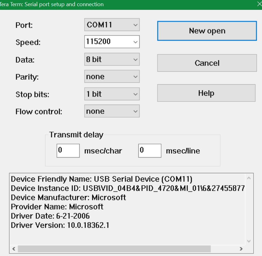
- After that, you will start getting the debug prints on the virtual com port (Teraterm) when the USB serial device (com x) is selected in the
Please try writing to SPI Flash, and share the debug prints so that we can know where exactly the writing fails
Regards,
Rashi
Rashi
- Mark as New
- Bookmark
- Subscribe
- Mute
- Subscribe to RSS Feed
- Permalink
- Report Inappropriate Content
Dear Rashi,
Great,thanks.
I will try and let you know soon.
BR
Steven.
- Mark as New
- Bookmark
- Subscribe
- Mute
- Subscribe to RSS Feed
- Permalink
- Report Inappropriate Content
Dear Rashi,
I have problem at step of :
"Then, power cycle the device and program again with the attached firmware, the device is expected to come up as "FX3" in the other devices section of the device manager. Manually bind the driver to the device as mentioned in Q1 of this KBA Trouble Shooting Guide for the FX3/FX3S/CX3 Enumeration - KBA222372
"
=>I can see FX3(it showed two FX3,instead of only one) in the other device,and select my Win7 ..x86..,but Windows said could not find the driver for my device ?
Stuck here ?
Any idea ?
BR
Steven.
- Mark as New
- Bookmark
- Subscribe
- Mute
- Subscribe to RSS Feed
- Permalink
- Report Inappropriate Content
Hello Steven,
Please refer to Figure 6 of the Adding Communication Device Class Interface to FX3 Firmware - KBA229099 KBA and let me know if this is how the device enumerates n Windows 7
If yes, please follow the steps mentioned below Figure 6 of the KBA and bind the driver manually
Regards,
Rashi
Rashi
- Mark as New
- Bookmark
- Subscribe
- Mute
- Subscribe to RSS Feed
- Permalink
- Report Inappropriate Content
Dear Rashi,
I followed the steps,I can successfully to install the second FX3 which its identification code is 02, after that, the usb com port show up as desibed, OK.
But I faced the problem of the first FX3 (code=0xff),follow the instructions always the same error, Windows said could not find the driver for my device ?
My computer is Win7 /32 bits.
BR
Steven.
- Mark as New
- Bookmark
- Subscribe
- Mute
- Subscribe to RSS Feed
- Permalink
- Report Inappropriate Content
Dear Rashi,
And yes to your question, my situation is the same as figure 6 of your mentioned.
Steven
- Mark as New
- Bookmark
- Subscribe
- Mute
- Subscribe to RSS Feed
- Permalink
- Report Inappropriate Content
Dear Rashi,
Thank you very much for your kindly support always.
But seems this problem bothered you too long.
I use a external programmer to program SPI chip and soldering onto board and it works fine for all custom boards.
So,I will go this way.
Thanks.
Best Regards.
Steven.
- Mark as New
- Bookmark
- Subscribe
- Mute
- Subscribe to RSS Feed
- Permalink
- Report Inappropriate Content
Dear Rashi,
Good news.
Seems I found the problem cause.
After I changed current +1.2V power rail from AMS1117-1.2V to share with FPGA +1.1V(produced by different power chip) power rail, every function runs normally.
Looks like my AMS1117-1.2V power rail produce inferior power quality.
I duplicated same procedures to all 5 boards and all works fine now with original control center.
Thank you very much for your kindly support.
Best Regards.
Steven.
- Mark as New
- Bookmark
- Subscribe
- Mute
- Subscribe to RSS Feed
- Permalink
- Report Inappropriate Content
Hello Steven,
Glad to hear that the problem of writing to SPI flash was solved by improving the power rail quality.
Thank you for the update
Regards,
Rashi
Rashi
- Mark as New
- Bookmark
- Subscribe
- Mute
- Subscribe to RSS Feed
- Permalink
- Report Inappropriate Content
Dear Rashi,
Thanks ,I will try it.
But seems it needs password to unzip ?
Best Regards
Steven Lin
International Business Development
Senior Manager
Kpower.
RashiV_61 於 2020/12/15 下午 04:05 寫道:
Cypress Semiconductor logo <http://www.cypress.com>
>
Cypress Developer Community
<https://community.cypress.com/?et=watches.email.thread>
>
FX3 Control center : programming of spi flash(M25P40) failed
reply from RashiV_61
<https://community.cypress.com/people/RashiV_61?et=watches.email.thread>
in /USB Superspeed Peripherals/ - View the full discussion
<https://community.cypress.com/message/269335?et=watches.email.thread#269335>
>