

- Mark as New
- Bookmark
- Subscribe
- Mute
- Subscribe to RSS Feed
- Permalink
- Report Inappropriate Content
Hi,
i have a Enclustra PM3 with Mars ZX3 Zynq 7000 SoC
On PM3 Board a FX3 3014 is assembled.
Because of the given schematic I can't use GPIO29 als FV Pin.
In GPIF II Designer I have changed FV to GPIO21
The Zynq generate Video Timing for 720p Video Output
The Pixel Clock is 100MHz, so I get ~80 fps
The IIC Interface is connected to a AT24 EEPROM and the IIC address is changed.
The FX3 configures the Eeprom instead of the image sensor, this works.
But in AMCAP the is ablosutely no information shown aboaut the camera. The software says Acess denied.
Wehe I activate the DEBUG_PRINT_FRAME_COUNT the console says: UVC: Completed 0 frames and 0 buffers
What is going wrong?
Solved! Go to Solution.
- Mark as New
- Bookmark
- Subscribe
- Mute
- Subscribe to RSS Feed
- Permalink
- Report Inappropriate Content
Hello,
Since the interface is 24-bit, the 32KB buffer size won't be usable since you can't load the correct DATA_COUNT and ADDR_COUNT in the GPIF registers (would be fractional values).
So, you can use any of 22KB or 25KB or 28KB as buffer sizes to accommodate the counter values correctly.
Please do the following to try and get it running:
1.) Firstly, change the DMA buffer size to 22KB so that you can load the DATA_COUNT and ADDR_COUNT in the GPIF registers.
CY_FX_EP_BULK_VIDEO_PKT_SIZE (0x400) //1024 Bytes
CY_FX_EP_BULK_VIDEO_PKTS_COUNT (0x16) //22
CY_FX_UVC_STREAM_BUF_COUNT (4)
CY_FX_UVC_STREAM_BUF_SIZE ((CY_FX_EP_BULK_VIDEO_PKTS_COUNT * CY_FX_EP_BULK_VIDEO_PKT_SIZE)) //22KB
Please change the DMA channel configuration as above.
2.) The DATA_COUNT and ADDR_COUNT in the GPIF registers would be loaded with 7503
((22*1024)-16)/3 = 7504 -1 = 7503
3.) Change the probe control, single payload size to 22KB and change the max video frame size in bytes to (1280*720*3)
0x00, 0x30, 0x2A, 0x00, /* Max video frame size in bytes */
0x00, 0x58, 0x00, 0x00, /* No. of bytes device can rx in single payload = 22 KB */
4.) Also, in the probe control you shared, the value of fps is set wrong.
To specify 80 fps, use 0x48, 0xE8, 0x01, 0x00 instead of 0x45, 0xE8, 0x01, 0x00
Regards,
Yashwant
- Mark as New
- Bookmark
- Subscribe
- Mute
- Subscribe to RSS Feed
- Permalink
- Report Inappropriate Content
Hello,
Can you please probe the FV LV lines and share them?
Also, which data format are you streaming from the sensor?
Is your application still based on UVC?
Regards,
Yashwant

- Mark as New
- Bookmark
- Subscribe
- Mute
- Subscribe to RSS Feed
- Permalink
- Report Inappropriate Content
- Mark as New
- Bookmark
- Subscribe
- Mute
- Subscribe to RSS Feed
- Permalink
- Report Inappropriate Content
Hello,
Can you please share the trace again with PCLK, FV and LV being shown?
The pervious didn't have clear info about PCLK and FV.
From the previous trace, this is what i can tell:
1.) Please ensure that as soon as FV is asserted, LV should also get asserted right at that same time but there is a significant delay between FV assertion and LV assertion in the above trace.
2.) Also, LV was stopped way before FV was de-asserted in the previous frame ( found from the trace) - Before the FV for next frame is asserted.
Please make sure that FPGA assert FV and LV at the same time and then only the device will start streaming.
Also, can you please share the UART debug logs in the next interaction as well?
Regards,
Yashwant
- Mark as New
- Bookmark
- Subscribe
- Mute
- Subscribe to RSS Feed
- Permalink
- Report Inappropriate Content
I think it works now.
On a nother PC with Linux and VLC I get an image.
Every 10 seconds the live image hangs for 2 seconds and then it runs for 10 seconds.
I would upgrade the system to 24 Bit RGB interface. Is there a Windows compatible GUID for 24 Bit RGB Raw data which rund with amcap, vlc virtualdub ..?
Thank you very much
- Mark as New
- Bookmark
- Subscribe
- Mute
- Subscribe to RSS Feed
- Permalink
- Report Inappropriate Content
I changed from the working 16 bit YUV Design to a 24 bit interface, but the design doesn't work.
In GPIFII Designer --> Data Bus width from 16 to 24
LD Data Count and LD ADDR Count to 5455
in cyfxuvcdscr :
| /* Class specific Uncompressed VS format descriptor 24-bit RGB */ | ||
| 0x1B, | /* Descriptor size */ | |
| 0x24, | /* Class-specific VS I/f Type */ | |
| 0x04, | /* Subtype : uncompressed format I/F */ | |
| 0x01, | /* Format desciptor index */ | |
| 0x01, | /* Number of frame descriptor followed */ | |
| /* GUID, globally unique identifier used to identify streaming-encoding format: YUY2 */ | ||
| 0x7D, 0xEB, 0x36, 0xE4, | /* MEDIASUBTYPE_RGB888 GUID: E436EB7D-524F-11CE-9F53-0020AF0BA770 */ | |
| 0x4F, 0x52, 0xCE, 0x11, | ||
| 0x9F, 0x53, 0x00, 0x20, | ||
| 0xAF, 0x0B, 0xA7, 0x70, | ||
| 0x18, | /* Number of bits per pixel */ | |
| 0x01, | /* Optimum Frame Index for this stream: 1 */ | |
| 0x10, | /* X dimension of 10 the picture aspect ratio; Non-interlaced */ | |
| 0x09, | /* Y dimension of the pictuer aspect ratio: Non-interlaced */ | |
| 0x00, | /* Interlace Flags: Progressive scanning, no interlace */ | |
| 0x00, | /* duplication of the video stream restriction: 0 - no restriction */ |
AND
| /* Class specific Uncompressed VS frame descriptor */ | ||
| 0x1E, | /* Descriptor size */ | |
| 0x24, | /* Descriptor type*/ | |
| 0x05, | /* Subtype: uncompressed frame I/F */ | |
| 0x01, | /* Frame Descriptor Index */ | |
| 0x01, | /* Still image capture method 1 supported */ | |
| 0x00, 0x05, | /* Width in pixel */ | |
| 0xD0, 0x02, | /* Height in pixel */ | |
| 0x00,0x00,0x78,0x69, | /* Min bit rate bits/s. 1280*720*24*80*/ | |
| 0x00,0x00,0x78,0x69, | /* Max bit rate bits/s. */ | |
| // | 0x00,0x00,0x50,0x46, | /* Min bit rate bits/s.1280*720*16*80 */ |
| // | 0x00,0x00,0x50,0x46, | /* Max bit rate bits/s. */ |
| 0x00,0x30,0x2A,0x00, | /* Maximum video or still frame size in bytes(Deprecated)1280*720*3*/ | |
| // | 0x00,0x20,0x1C,0x00, | /* Maximum video or still frame size in bytes(Deprecated) 1280*720*2*/ |
| 0x48, 0xE8, 0x01, 0x00, | /* 80fps */ | |
| 0x01, | ||
| 0x48,0xE8,0x01,0x00, |
The Design does'nt work.
UART Print the followig message:
.....
.....
Application Stopped
Application Started
UVC: Completed 0 frames and 0 buffers
DMA Reset Event: Frame timer overflow, time period = 76
Application Stopped
Application Started
UVC: Completed 0 frames and 0 buffers
DMA Reset Event: Frame timer overflow, time period = 76
Application Stopped
Application Started
UVC: Completed 0 frames and 0 buffers
DMA Reset Event: Frame timer overflow, time period = 76
Application Stopped
Application Started
UVC: Completed 0 frames and 0 buffers
DMA Reset Event: Frame timer overflow, time period = 76
Application Stopped
Application Stopped after 30 Commit buffer failures
UVC: Completed 0 frames and 0 buffers
- Mark as New
- Bookmark
- Subscribe
- Mute
- Subscribe to RSS Feed
- Permalink
- Report Inappropriate Content
Hello,
Can you please share the size and count of DMA buffers that you have allocated while creating the DMA channel?
Can you please share wireshark traces for the situation when you saw that the firmware was working on linux PC (Interaction No: 5)?
Also, can you please share wireshark traces for the above case when you are using 24-bit RGB stream?
Regards,
Yashwant
- Mark as New
- Bookmark
- Subscribe
- Mute
- Subscribe to RSS Feed
- Permalink
- Report Inappropriate Content
Do you mean these DMA settings:
/* UVC Video Streaming Endpoint Packet Size */
#define CY_FX_EP_BULK_VIDEO_PKT_SIZE (0x400) /* 1024 Bytes */
/* UVC Video Streaming Endpoint Packet Count */
#define CY_FX_EP_BULK_VIDEO_PKTS_COUNT (0x10) /* 16 packets (burst of 16) per DMA buffer. */
/* DMA buffer size used for video streaming. */
#define CY_FX_UVC_STREAM_BUF_SIZE (CY_FX_EP_BULK_VIDEO_PKTS_COUNT * CY_FX_EP_BULK_VIDEO_PKT_SIZE) /* 16 KB */
/* Maximum video data that can be accommodated in one DMA buffer. */
#define CY_FX_UVC_BUF_FULL_SIZE (CY_FX_UVC_STREAM_BUF_SIZE - 16)
/* Number of DMA buffers per GPIF DMA thread. */
#define CY_FX_UVC_STREAM_BUF_COUNT (4)
/* Low Byte - UVC Video Streaming Endpoint Packet Size */
#define CY_FX_EP_BULK_VIDEO_PKT_SIZE_L (uint8_t)(CY_FX_EP_BULK_VIDEO_PKT_SIZE & 0x00FF)
/* High Byte - UVC Video Streaming Endpoint Packet Size and No. of BULK packets */
#define CY_FX_EP_BULK_VIDEO_PKT_SIZE_H (uint8_t)((CY_FX_EP_BULK_VIDEO_PKT_SIZE & 0xFF00) >> 😎
/* Maximum commit buffer failures to detect a stop streaming event in a MAC OS */
#define CY_FX_UVC_MAX_COMMIT_BUF_FAILURE_CNT (30)
I have no Wireshark on the Linux PC because it's a Knoppix, sorry,
Thanks
Richard
- Mark as New
- Bookmark
- Subscribe
- Mute
- Subscribe to RSS Feed
- Permalink
- Report Inappropriate Content
Hi Richard,
We would firstly need to identify if the image sensor is streaming any data to FX3 or not and if it does, is FX3 not able to pass the data on to the host.
So, for the first one, i would need you to share the FV, LV and PCLK traces from an oscilloscope and make sure that they are okay. If that is not proper, means that data from image sensor is not coming to FX3.
After that, i would need you to share a wireshark trace of the working and non-working scenarios in a windows PC or wherever you can get a software analyzer trace from to understand if the data from image sensor is reaching the host or not or is the host not issuing any request to read data at all.
The above things are necessary to identify what is causing the problem exactly and without them, its not possible to understand the source of the problem.
Also, in order to stream RGB, you will have to write your own custom host application as there is no available host applications that can stream RGB raw data.
Regards,
Yashwant
- Mark as New
- Bookmark
- Subscribe
- Mute
- Subscribe to RSS Feed
- Permalink
- Report Inappropriate Content
Thank you for your response.
I've captured now the data with wireshark,
With 16-bit Interface it is working fine, the image is shown in the application, so the fvalid lvalid interface works.
wireshark capture a lot of data in this working szenario, so the dump is very big. Which data do you need?
In 24-bit mode, with is not working, i have capured some data too. This dump is attached.
Thanks a lot
Richard
- Mark as New
- Bookmark
- Subscribe
- Mute
- Subscribe to RSS Feed
- Permalink
- Report Inappropriate Content
Hello Richard,
The wireshark only shows that one buffer is being committed to the host and nothing else.
Can you do the following and then share the UART traces and the results:
1.) Comment #define FRAME_TIMER_ENABLE in uvc.h file so that the application won't have a DMA reset event when the timer overflows and share the UART logs.
2.) Please share the FV, LV and PCLK oscilloscope traces for the 24-bit interface scenario, i am still waiting on them.
3.) Please define a global variable and initialize to " 0 " in the firmware and increment the variable in DmaCallback when the CY_U3P_DMA_CB_PROD_EVENT occurs after the CommitBuffer API and print the variable in the for( ; ; ) loop and share the UART log.
Please do the following and share the results.
Regards,
Yashwant
- Mark as New
- Bookmark
- Subscribe
- Mute
- Subscribe to RSS Feed
- Permalink
- Report Inappropriate Content
YashwantK_46 schrieb:
Hello Richard,
The wireshark only shows that one buffer is being committed to the host and nothing else.
Can you do the following and then share the UART traces and the results:
1.) Comment #define FRAME_TIMER_ENABLE in uvc.h file so that the application won't have a DMA reset event when the timer overflows and share the UART logs.
2.) Please share the FV, LV and PCLK oscilloscope traces for the 24-bit interface scenario, i am still waiting on them.
3.) Please define a global variable and initialize to " 0 " in the firmware and increment the variable in DmaCallback when the CY_U3P_DMA_CB_PROD_EVENT occurs after the CommitBuffer API and print the variable in the for( ; ; ) loop and share the UART log.
Please do the following and share the results.
Regards,
Yashwant
I've tested 1.) 2.) and 3.), there is no extra information in the uart log.
Is this the right count position fo 3.)?
/* Commit Buffer to USB*/
status = CyU3PDmaMultiChannelCommitBuffer (chHandle, (dmaBuffer.count + CY_FX_UVC_MAX_HEADER), 0);
if (status == CY_U3P_SUCCESS)
{
#ifdef DEBUG_PRINT_FRAME_COUNT
glDmaDone++;
#endif
commit++;
}
else
{
not_commit++;
if(glDmaResetFlag == CY_FX_UVC_DMA_RESET_EVENT_NOT_ACTIVE)
{
glDmaResetFlag = CY_FX_UVC_DMA_RESET_COMMIT_BUFFER_FAILURE;
CyU3PEventSet(&glFxUVCEvent, CY_FX_UVC_DMA_RESET_EVENT, CYU3P_EVENT_OR);
}
break;
}
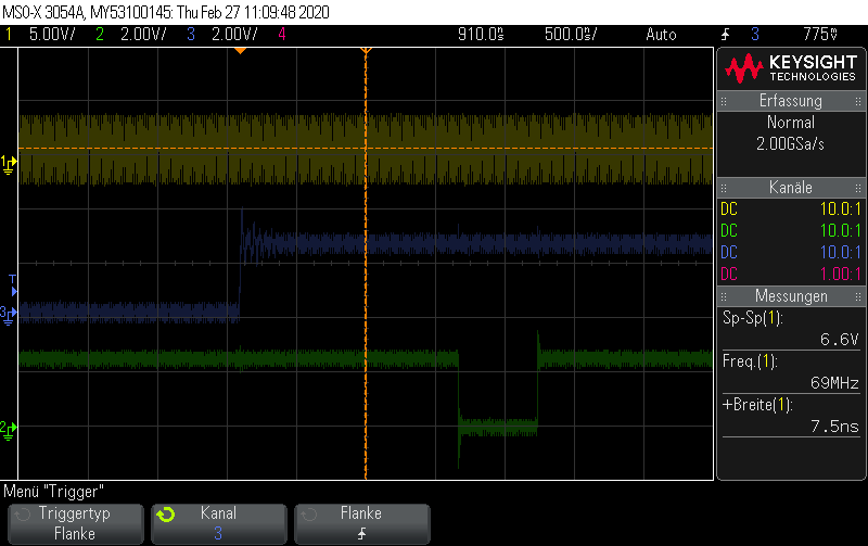
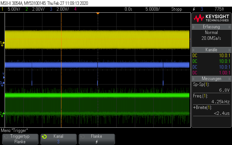
to 2.) there is no other scope than shown on RiFu_3006586 10.12.2019 23:28 above. Pixelclock is 100MHz.VSYNC is the yellow line, HSNYC the green one.
It's the same timing that works in 16 bit mode.
- Mark as New
- Bookmark
- Subscribe
- Mute
- Subscribe to RSS Feed
- Permalink
- Report Inappropriate Content
Hello Richard,
1.) Please share the UART debug logs after commenting the #define FRAME_TIMER_ENABLE with me.
2.) Please share the oscilloscope traces with PCLK, FV and LV clrealy visible to me. The last trace that you shared isn't clear enough to understand.
For 3.), do it as shown below and see the logs
uint32_t Prod = 0; //initializing variable for prod
uint32_t Cons = 0; //initializing variable for cons
In DmaCallback()
{
if (type == CY_U3P_DMA_CB_PROD_EVENT)
{
status = CyU3PDmaMultiChannelCommitBuffer(chHandle, dmaBuffer.count, 0);
//increment the variable after the above line on Sucess
Prod++;
}
else if (type == CY_U3P_DMA_CB_CONS_EVENT)
{
Cons++;
}
}
in for (;;)
use the below line:
CyU3PDebugPrint(4,"\n\r Prod = %d Cons = %d", Prod, Cons);
Do the above steps and share the UART log with me so that I can compare it with the wireshark trace that you have shared.
Regards,
Yashwant
- Mark as New
- Bookmark
- Subscribe
- Mute
- Subscribe to RSS Feed
- Permalink
- Report Inappropriate Content
When I reduce the pixelclock from 100MHz to 66 MHz, it works fine in 24 bit.
- Mark as New
- Bookmark
- Subscribe
- Mute
- Subscribe to RSS Feed
- Permalink
- Report Inappropriate Content
Hello Richard,
Changing the pixel clock would directly affect your fps. Can you check if the fps and throughput that you are getting is satisfactory to you?
If you don't want the fps to be effected even after changing the pixel clock, you will have to make sure that the total frame time is similar to when the pixel clock was 100MHz. You can do this by reducing the H-blanking and V-blanking to get up to the satisfactory fps range that you want to achieve.
So, please modify the blanking times so that you meet the required fps rate in your design.
Regards,
Yashwant
- Mark as New
- Bookmark
- Subscribe
- Mute
- Subscribe to RSS Feed
- Permalink
- Report Inappropriate Content
YashwantK_46 schrieb:
Hello Richard,
Changing the pixel clock would directly affect your fps. Can you check if the fps and throughput that you are getting is satisfactory to you?
If you don't want the fps to be effected even after changing the pixel clock, you will have to make sure that the total frame time is similar to when the pixel clock was 100MHz. You can do this by reducing the H-blanking and V-blanking to get up to the satisfactory fps range that you want to achieve.
So, please modify the blanking times so that you meet the required fps rate in your design.
Regards,
Yashwant
I've tested some different pixelclocks with constant video timing, the maximum pixelclock where a image is shown is about 70MHz.
Where is here the bottleneck, I thought that 100MHz is possible?
- Mark as New
- Bookmark
- Subscribe
- Mute
- Subscribe to RSS Feed
- Permalink
- Report Inappropriate Content
Hello Richard,
100MHz over GPIF II interface and image sensor is possible.
We need to understand if there is any issue on the FPGA side.
So, please share the following when you are using pixelclock more than 70MHz:
1.) PCLK, FV and LV oscilloscope traces.
2.) UART Debug prints.
Please share the following so that we can understand the issue better.
Regards,
Yashwant
- Mark as New
- Bookmark
- Subscribe
- Mute
- Subscribe to RSS Feed
- Permalink
- Report Inappropriate Content
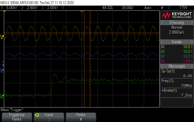
Scope 0,2,3,4 show the timing @70MHz Pixclock (Yellow= Clock Green= Hsync Blue= Vsync)
This works and image is shown on PC
Log @70 MHZ:
Prod = 494901 Cons = 494877UVC: Completed 0 frames and 0 buffers
Prod = 494901 Cons = 494877UVC: Completed 0 frames and 0 buffers
Prod = 494901 Cons = 494877Application Started
UVC: Completed 0 frames and 0 buffers
Prod = 504533 Cons = 504509UVC: Completed 57 frames and 0 buffers
Prod = 514166 Cons = 514142UVC: Completed 114 frames and 0 buffers
Prod = 523799 Cons = 523774UVC: Completed 171 frames and 0 buffers
Prod = 533432 Cons = 533408UVC: Completed 228 frames and 0 buffers
Prod = 543065 Cons = 543041UVC: Completed 285 frames and 0 buffers
Prod = 552698 Cons = 552674UVC: Completed 342 frames and 0 buffers
Prod = 562331 Cons = 562306UVC: Completed 399 frames and 0 buffers
Prod = 571964 Cons = 571940UVC: Completed 456 frames and 0 buffers
Prod = 581597 Cons = 581572UVC: Completed 513 frames and 0 buffers
Prod = 591230 Cons = 591206UVC: Completed 570 frames and 0 buffers
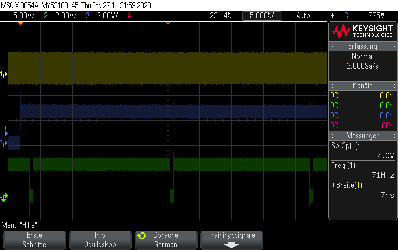
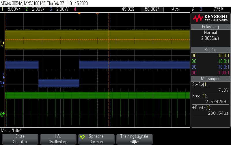
Scope 6,7,8,9 @75MHz Pixelclock, no Image is shown on PC
The timing is the same counted in clocks (clock was increased from 70MHz to 75 MHz)
Log:
Prod = 0 Cons = 0Entering USB Suspend Mode
USBSetupCB:In SET_FTR 0::0
Leaving Suspend Mode
UVC: Completed 0 frames and 0 buffers
Prod = 0 Cons = 0Application Started
UVC: Completed 0 frames and 0 buffers
Prod = 447 Cons = 479DMA Reset Event: Commit buffer failure
Application Stopped
Application Started
UVC: Completed 0 frames and 0 buffers
Prod = 564 Cons = 628DMA Reset Event: Commit buffer failure
Application Stopped
Application Started
UVC: Completed 0 frames and 0 buffers
Prod = 697 Cons = 785DMA Reset Event: Commit buffer failure
Application Stopped
Application Started
UVC: Completed 0 frames and 0 buffers
Prod = 942 Cons = 1093DMA Reset Event: Commit buffer failure
Application Stopped
Application Started
UVC: Completed 0 frames and 0 buffers
- Mark as New
- Bookmark
- Subscribe
- Mute
- Subscribe to RSS Feed
- Permalink
- Report Inappropriate Content
Hello,
1.) Can you please check if you have set the setSysClk400 parameter in the CyU3PDeviceInit() API and if not, please use the following code snippet and replace the API with the code below:
/* setSysClk400 clock configurations */
clkCfg.setSysClk400 = CyTrue; /* FX3 device's master clock is set to a frequency > 400 MHz */
clkCfg.cpuClkDiv = 2; /* CPU clock divider */
clkCfg.dmaClkDiv = 2; /* DMA clock divider */
clkCfg.mmioClkDiv = 2; /* MMIO clock divider */
clkCfg.useStandbyClk = CyFalse; /* device has no 32KHz clock supplied */
clkCfg.clkSrc = CY_U3P_SYS_CLK; /* Clock source for a peripheral block */
/* Initialize the device */
status = CyU3PDeviceInit (&clkCfg);
if (status != CY_U3P_SUCCESS)
{
goto handle_fatal_error;
}
2.) Since there are DMA Reset Event: Commit buffer failure events in the above UART logs that you shared, can you please increase the DMA buffers size in your firmware and then try it?
Also, please make sure that you have one through the following KBA: Invalid Sequence Error in Multi-Channel Commit Buffer - KBA218830
And then share the UART debug logs again for >70MHz pixel clock.
3.) To remove the Frame Timer overflow reset events, please comment out the #define FRAME_TIMER_ENABLE in the uvc.h file of your firmware project.
Regards,
Yashwant
- Mark as New
- Bookmark
- Subscribe
- Mute
- Subscribe to RSS Feed
- Permalink
- Report Inappropriate Content
/* setSysClk400 clock configurations */
clkCfg.setSysClk400 = CyTrue; /* FX3 device's master clock is set to a frequency > 400 MHz */
clkCfg.cpuClkDiv = 2; /* CPU clock divider */
clkCfg.dmaClkDiv = 2; /* DMA clock divider */
clkCfg.mmioClkDiv = 2; /* MMIO clock divider */
clkCfg.useStandbyClk = CyFalse; /* device has no 32KHz clock supplied */
clkCfg.clkSrc = CY_U3P_SYS_CLK; /* Clock source for a peripheral block */
is done.
The device now runs with a bit more than 70 MHz, but not @100MHz
Where I can increase the DMA Buffer Size?
I only found thisin uvc.h:
/* UVC Video Streaming Endpoint Packet Size */
#define CY_FX_EP_BULK_VIDEO_PKT_SIZE (0x400) /* 1024 Bytes */
/* UVC Video Streaming Endpoint Packet Count */
#define CY_FX_EP_BULK_VIDEO_PKTS_COUNT (0x10) /* 16 packets (burst of 16) per DMA buffer. */
- Mark as New
- Bookmark
- Subscribe
- Mute
- Subscribe to RSS Feed
- Permalink
- Report Inappropriate Content
Hello,
In uvc.h file, you will need to check with the following:
1.) Change value of CY_FX_EP_BULK_VIDEO_PKTS_COUNT from 0x10 to 0x20 and in uvc.c, CY_FX_UVC_STREAM_BUF_COUNT from 4 to 3.
2.) Change value of CY_FX_EP_BULK_VIDEO_PKTS_COUNT from 0x10 to 0x30 and in uvc.c, CY_FX_UVC_STREAM_BUF_COUNT from 4 to 2.
This will change the buffer sizes and counts for the streaming DMA channel as:
1.) 32KB with 3 buffers,
2.) 48KB with 2 buffers.
Please do the following and check if you are able to stream video at higher pixel clock.
What is the maximum clock that you are able to stream at after change the sysClk400 parameter?
Regards,
Yashwant
- Mark as New
- Bookmark
- Subscribe
- Mute
- Subscribe to RSS Feed
- Permalink
- Report Inappropriate Content
Test with 80 MHz clock:
1.) Change value of CY_FX_EP_BULK_VIDEO_PKTS_COUNT from 0x10 to 0x20 and in uvc.c, CY_FX_UVC_STREAM_BUF_COUNT from 4 to 3.
2.) Change value of CY_FX_EP_BULK_VIDEO_PKTS_COUNT from 0x10 to 0x30 and in uvc.c, CY_FX_UVC_STREAM_BUF_COUNT from 4 to 2.
No image is shown in the application with both settings,
Log:
Prod = 0 Cons = 0Application Started
UVC: Completed 0 frames and 0 buffers
Prod = 3672 Cons = 3671UVC: Completed 64 frames and 24 buffers
Prod = 7357 Cons = 7355UVC: Completed 129 frames and 4 buffers
Prod = 11043 Cons = 11041UVC: Completed 193 frames and 42 buffers
Prod = 14726 Cons = 14726UVC: Completed 258 frames and 20 buffers
Prod = 18411 Cons = 18411UVC: Completed 323 frames and 0 buffers
Prod = 22097 Cons = 22096UVC: Completed 387 frames and 38 buffers
Prod = 25782 Cons = 25780UVC: Completed 452 frames and 18 buffers
Prod = 29467 Cons = 29466UVC: Completed 516 frames and 55 buffers
Prod = 33151 Cons = 33151UVC: Completed 581 frames and 34 buffers
Prod = 36836 Cons = 36835UVC: Completed 646 frames and 14 buffers
Prod = 40522 Cons = 40521UVC: Completed 710 frames and 52 buffers
Prod = 44205 Cons = 44205UVC: Completed 775 frames and 32 buffers
- Mark as New
- Bookmark
- Subscribe
- Mute
- Subscribe to RSS Feed
- Permalink
- Report Inappropriate Content
Hello,
Along with the buffer size and count changes, you will have to change the last parameter in the glProbeCtrl array, the payload size in USB 3.0 connection as shown:
/* UVC Probe Control Settings for a USB 3.0 connection. */
uint8_t glProbeCtrl[CY_FX_UVC_MAX_PROBE_SETTING] = {
0x00, 0x00, /* bmHint : no hit */
0x01, /* Use 1st Video format index */
0x01, /* Use 1st Video frame index */
0x15, 0x16, 0x05, 0x00, /* Desired frame interval in the unit of 100ns: 30 fps */
0x00, 0x00, /* Key frame rate in key frame/video frame units: only applicable
to video streaming with adjustable compression parameters */
0x00, 0x00, /* PFrame rate in PFrame / key frame units: only applicable to
video streaming with adjustable compression parameters */
0x00, 0x00, /* Compression quality control: only applicable to video streaming
with adjustable compression parameters */
0x00, 0x00, /* Window size for average bit rate: only applicable to video
streaming with adjustable compression parameters */
0x00, 0x00, /* Internal video streaming i/f latency in ms */
0x00, 0x48, 0x3F, 0x00, /* Max video frame size in bytes */
0x00, 0x40, 0x00, 0x00, /* No. of bytes device can rx in single payload = 16 KB */
#ifndef FX3_UVC_1_0_SUPPORT
/* UVC 1.1 Probe Control has additional fields from UVC 1.0 */
0x00, 0x60, 0xE3, 0x16, /* Device Clock */
0x00, /* Framing Information - Ignored for uncompressed format*/
0x00, /* Preferred payload format version */
0x00, /* Minimum payload format version */
0x00 /* Maximum payload format version */
#endif
};
This payload size should either be equal to the buffer size or greater than that but shouldn't be less.
Please try the above method as share your observations.
Regards,Yashwant
- Mark as New
- Bookmark
- Subscribe
- Mute
- Subscribe to RSS Feed
- Permalink
- Report Inappropriate Content
| 0x00, 0x40, 0x00, 0x00, | /* No. of bytes device can rx in single payload = 16 KB */ |
and
| 0x00, 0x80, 0x00, 0x00, | /* No. of bytes device can rx in single payload = 16 KB */ |
do not work.
If I set the pixelclock to 70 MHZ and
| #define CY_FX_UVC_STREAM_BUF_COUNT | (3) |
#define CY_FX_EP_BULK_VIDEO_PKTS_COUNT (0x20)
there is no image shown.
When I change to
#define CY_FX_EP_BULK_VIDEO_PKTS_COUNT (0x10)
runs.
Should I change LD_DATA Count and LD_Addr_Count to 10916 ?
- Mark as New
- Bookmark
- Subscribe
- Mute
- Subscribe to RSS Feed
- Permalink
- Report Inappropriate Content
Hello,
Yes you will have to change the DATA_count and ADDR_count in the state machine too.
Use the formula that is shown below to get the count that needs to be loaded in the counters.

Regards,
Yashwant
- Mark as New
- Bookmark
- Subscribe
- Mute
- Subscribe to RSS Feed
- Permalink
- Report Inappropriate Content
Is 10916 correct?
(32768 - 16) =32752
32752/ (24/8) =10917,3 -> 10917 -1 = 10916
Is this change correct?
3*10917 = 32751
| #define CY_FX_UVC_BUF_FULL_SIZE | 32751//(CY_FX_UVC_STREAM_BUF_SIZE - 16) |
- Mark as New
- Bookmark
- Subscribe
- Mute
- Subscribe to RSS Feed
- Permalink
- Report Inappropriate Content
Hello,
Since the interface is 24-bit,
You will have to use #define CY_FX_UVC_BUF_FULL_SIZE 24592 //(CY_FX_UVC_STREAM_BUF_SIZE (24KB) + 16)
Also, then the count values would be:
24576/3 = 8192 -1 = 8191
Please try the following and share your findings.
Regards,
Yashwant
- Mark as New
- Bookmark
- Subscribe
- Mute
- Subscribe to RSS Feed
- Permalink
- Report Inappropriate Content
/* UVC Video Streaming Endpoint Packet Size */
#define CY_FX_EP_BULK_VIDEO_PKT_SIZE (0x400) /* 1024 Bytes */
/* UVC Video Streaming Endpoint Packet Count */
#define CY_FX_EP_BULK_VIDEO_PKTS_COUNT (0x20) /* 16 packets (burst of 16) per DMA buffer. */
/* DMA buffer size used for video streaming. */
//#define CY_FX_UVC_STREAM_BUF_SIZE (CY_FX_EP_BULK_VIDEO_PKTS_COUNT * CY_FX_EP_BULK_VIDEO_PKT_SIZE) /* 16 KB */
#define CY_FX_UVC_STREAM_BUF_SIZE (CY_FX_EP_BULK_VIDEO_PKTS_COUNT * CY_FX_EP_BULK_VIDEO_PKT_SIZE) /*32 KB */
/* Maximum video data that can be accommodated in one DMA buffer. */
//#define CY_FX_UVC_BUF_FULL_SIZE (CY_FX_UVC_STREAM_BUF_SIZE - 16)
#define CY_FX_UVC_BUF_FULL_SIZE 24592 //(CY_FX_UVC_STREAM_BUF_SIZE (24KB) + 16)
/* Number of DMA buffers per GPIF DMA thread. */
#define CY_FX_UVC_STREAM_BUF_COUNT (2)
LD_ADD_COUNT = LD_DATA_COUNT= 8191
No image, but it seems the number of frame increases very fast
Prod = 6129 Cons = 6129UVC: Completed 6132 frames and 0 buffers
Prod = 12374 Cons = 12373UVC: Completed 12376 frames and 0 buffers
Prod = 18617 Cons = 18617UVC: Completed 18620 frames and 0 buffers
Prod = 24860 Cons = 24860UVC: Completed 24860 frames and 0 buffers
Prod = 31101 Cons = 31100UVC: Completed 31103 frames and 0 buffers
Prod = 37345 Cons = 37344UVC: Completed 37347 frames and 0 buffers
Prod = 43589 Cons = 43588UVC: Completed 43591 frames and 0 buffers
Prod = 49832 Cons = 49832UVC: Completed 49833 frames and 0 buffers
Prod = 56072 Cons = 56071UVC: Completed 56074 frames and 0 buffers
- Mark as New
- Bookmark
- Subscribe
- Mute
- Subscribe to RSS Feed
- Permalink
- Report Inappropriate Content
Hello,
Thank you for the information.
Can you please tell what is the fps of the video stream at 70MHz pixel clock and >75MHz (let's say 80MHz) pixel clock that you can see when you probe the FV and LV lines on the sensor?
Also, please share traces of the FV and LV of a frame (FV active + FV blanking) from the sensor side with the time differences in both the cases of pixel clock?
Regards,
Yashwant
- Mark as New
- Bookmark
- Subscribe
- Mute
- Subscribe to RSS Feed
- Permalink
- Report Inappropriate Content
56fps @ 70 MHz
64,6fps @80MHz
it's a standard 720p video timing
- Mark as New
- Bookmark
- Subscribe
- Mute
- Subscribe to RSS Feed
- Permalink
- Report Inappropriate Content
Hello,
Since the change in pixel clock increases the fps, the new fps is not added in the probe control or the descriptors and hence that's the reason you don't see any image.
So, you will need to mention the new fps in the probe control structures and the descriptors.
Also, once you have modified the firmware, can you please share it so that i can check the descriptors and probe control structures in your firmware?
Regards,
Yashwant
- Mark as New
- Bookmark
- Subscribe
- Mute
- Subscribe to RSS Feed
- Permalink
- Report Inappropriate Content
When the video timing @ 70 MHz runs with the 16kb buffer, and I change the buffer to 32kb it doesn't work.
/* UVC Probe Control Settings for a USB 3.0 connection. */
uint8_t glProbeCtrl[CY_FX_UVC_MAX_PROBE_SETTING] = {
0x00, 0x00, /* bmHint : no hit */
0x01, /* Use 1st Video format index */
0x01, /* Use 1st Video frame index */
0x45, 0xE8, 0x01, 0x00, /* Desired frame interval in the unit of 100ns: 30 fps */
0x00, 0x00, /* Key frame rate in key frame/video frame units: only applicable
to video streaming with adjustable compression parameters */
0x00, 0x00, /* PFrame rate in PFrame / key frame units: only applicable to
video streaming with adjustable compression parameters */
0x00, 0x00, /* Compression quality control: only applicable to video streaming
with adjustable compression parameters */
0x00, 0x00, /* Window size for average bit rate: only applicable to video
streaming with adjustable compression parameters */
0x00, 0x00, /* Internal video streaming i/f latency in ms */
0x00, 0x48, 0x3F, 0x00, /* Max video frame size in bytes */
0x00, 0x80, 0x00, 0x00, /* No. of bytes device can rx in single payload = 32 KB */
#ifndef FX3_UVC_1_0_SUPPORT
/* UVC 1.1 Probe Control has additional fields from UVC 1.0 */
0x00, 0x60, 0xE3, 0x16, /* Device Clock */
0x00, /* Framing Information - Ignored for uncompressed format*/
0x00, /* Preferred payload format version */
0x00, /* Minimum payload format version */
0x00 /* Maximum payload format version */
#endif
};
| /* Class specific Uncompressed VS frame descriptor */ | ||
| 0x1E, | /* Descriptor size */ | |
| 0x24, | /* Descriptor type*/ | |
| 0x05, | /* Subtype: uncompressed frame I/F */ | |
| 0x01, | /* Frame Descriptor Index */ | |
| 0x01, | /* Still image capture method 1 supported */ | |
| 0x00, 0x05, | /* Width in pixel */ | |
| 0xD0, 0x02, | /* Height in pixel */ | |
| 0x00,0x00,0x78,0x69, | /* Min bit rate bits/s. 1280*720*24*80*/ | |
| 0x00,0x00,0x78,0x69, | /* Max bit rate bits/s. */ | |
| // | 0x00,0x00,0x50,0x46, | /* Min bit rate bits/s.1280*720*16*80 */ |
| // | 0x00,0x00,0x50,0x46, | /* Max bit rate bits/s. */ |
| 0x00,0x30,0x2A,0x00, | /* Maximum video or still frame size in bytes(Deprecated)1280*720*3*/ | |
| // | 0x00,0x20,0x1C,0x00, | /* Maximum video or still frame size in bytes(Deprecated) 1280*720*2*/ |
| 0x48, 0xE8, 0x01, 0x00, | /* 80fps */ | |
| 0x01, | ||
| 0x48,0xE8,0x01,0x00, |
- Mark as New
- Bookmark
- Subscribe
- Mute
- Subscribe to RSS Feed
- Permalink
- Report Inappropriate Content
Hello,
Since the interface is 24-bit, the 32KB buffer size won't be usable since you can't load the correct DATA_COUNT and ADDR_COUNT in the GPIF registers (would be fractional values).
So, you can use any of 22KB or 25KB or 28KB as buffer sizes to accommodate the counter values correctly.
Please do the following to try and get it running:
1.) Firstly, change the DMA buffer size to 22KB so that you can load the DATA_COUNT and ADDR_COUNT in the GPIF registers.
CY_FX_EP_BULK_VIDEO_PKT_SIZE (0x400) //1024 Bytes
CY_FX_EP_BULK_VIDEO_PKTS_COUNT (0x16) //22
CY_FX_UVC_STREAM_BUF_COUNT (4)
CY_FX_UVC_STREAM_BUF_SIZE ((CY_FX_EP_BULK_VIDEO_PKTS_COUNT * CY_FX_EP_BULK_VIDEO_PKT_SIZE)) //22KB
Please change the DMA channel configuration as above.
2.) The DATA_COUNT and ADDR_COUNT in the GPIF registers would be loaded with 7503
((22*1024)-16)/3 = 7504 -1 = 7503
3.) Change the probe control, single payload size to 22KB and change the max video frame size in bytes to (1280*720*3)
0x00, 0x30, 0x2A, 0x00, /* Max video frame size in bytes */
0x00, 0x58, 0x00, 0x00, /* No. of bytes device can rx in single payload = 22 KB */
4.) Also, in the probe control you shared, the value of fps is set wrong.
To specify 80 fps, use 0x48, 0xE8, 0x01, 0x00 instead of 0x45, 0xE8, 0x01, 0x00
Regards,
Yashwant