

- Mark as New
- Bookmark
- Subscribe
- Mute
- Subscribe to RSS Feed
- Permalink
- Report Inappropriate Content
Hi,
I use FX3 with an image sensor. Also, i need to use it to communicate with a FPGA. A simple GPIFToUSB project is sufficient for this. However, i don't know how to merge these two projects. Can UVC and GPIFToUSB work together with different threads?
Another problem is the number of pins. 16-bits are used for UVC, but if i add the GPIFToUsb states same data bus also will be used for driving data. Another question is that if a make the data bus 24-bits, can i use this bus seperately such as 23:16 for gpiftousb and 15:0 for UVC?
Solved! Go to Solution.
- Labels:
-
USB Superspeed Peripherals
- Mark as New
- Bookmark
- Subscribe
- Mute
- Subscribe to RSS Feed
- Permalink
- Report Inappropriate Content
Hello,
Your previous reply seems to be confusing. Initially, you mentioned that the image data is transferred from an FPGA using the UVC firmware provided in AN75779. But later, you mentioned that the image sensor does not have an I2C interface. Is the first sentence a mistake? Can you please clarify?
Also, please let me know how was the brightness controlled by using another FPGA.
As you might be knowing, FX3 can only run one GPIF II state machine at a time. Suppose you are using the AN75779 state machine. If you try to modify the GPIF II state machine in such a way that the data bus width is changed from 16 to 24 bits for accepting the FPGA data, the following problems will occur:
1. The data will be sampled based on the interface signals provided by the image sensor (FV and LV).
2. For each PCLK, FX3 will sample 24 bits and this will be sent to the host. The host application needs to be modified so that the first 8 bits coming from the FPGA can be separated from the remaining 16 bit pixel data. Otherwise, you will not see an image on the host side.
Jayakrishna
- Mark as New
- Bookmark
- Subscribe
- Mute
- Subscribe to RSS Feed
- Permalink
- Report Inappropriate Content
Hello,
Please let me know what exactly is the end application so that we can understand it better.
Also, please let me know the GPIF II state machines that is used for both the projects. Are you looking forward to integrate both the state machines into a single one? Please elaborate the requirement so that we can suggest the best possible solution.
Jayakrishna

- Mark as New
- Bookmark
- Subscribe
- Mute
- Subscribe to RSS Feed
- Permalink
- Report Inappropriate Content
Thank you for your reply.
I am taking the image data from a FPGA and UVC firmware provided in AN75779 is doing a good job for me. However, i need to change some parameters of the camera in real time, so i need another communication path between the FPGA board and computer (My image sensor does not have an I2C interface). For that i was using another USB board, Superseed explorer kit. This system works but now i want to work with a single USB board.
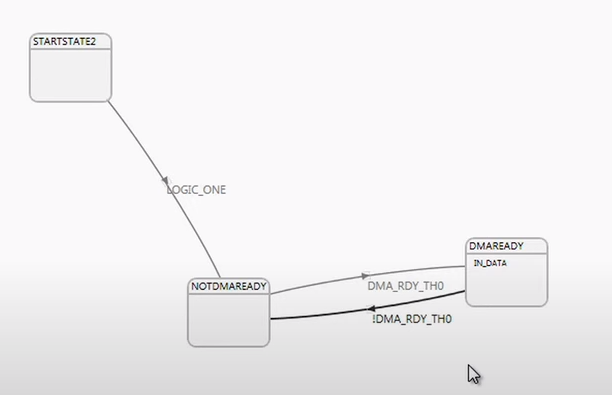
I am not familiar with the details of the state machines but i am editing the original state diagrams of both UVC and GpifToUsb examples. As you said, i want to integrate both state machines into a single one. State machines of the projects are attached to this message.
Edit: A mistake in the gpiftousb state diagram, action in the DMAREADY state should be DR_DATA
- Mark as New
- Bookmark
- Subscribe
- Mute
- Subscribe to RSS Feed
- Permalink
- Report Inappropriate Content
Hello,
Your previous reply seems to be confusing. Initially, you mentioned that the image data is transferred from an FPGA using the UVC firmware provided in AN75779. But later, you mentioned that the image sensor does not have an I2C interface. Is the first sentence a mistake? Can you please clarify?
Also, please let me know how was the brightness controlled by using another FPGA.
As you might be knowing, FX3 can only run one GPIF II state machine at a time. Suppose you are using the AN75779 state machine. If you try to modify the GPIF II state machine in such a way that the data bus width is changed from 16 to 24 bits for accepting the FPGA data, the following problems will occur:
1. The data will be sampled based on the interface signals provided by the image sensor (FV and LV).
2. For each PCLK, FX3 will sample 24 bits and this will be sent to the host. The host application needs to be modified so that the first 8 bits coming from the FPGA can be separated from the remaining 16 bit pixel data. Otherwise, you will not see an image on the host side.
Jayakrishna