


- Mark as New
- Bookmark
- Subscribe
- Mute
- Subscribe to RSS Feed
- Permalink
- Report Inappropriate Content
Hi all,
First, my goal is a streamer application (non-uvc) which capable to stream RAW data.
The HW setup - I'm using the CYUSB3KIT-003 with the Aptina sensor (According to an75779).
About the firmware:
1. I follow this post FX3 / CX3 Firmware for Streaming RAW Image Data using Cypress Driver for non-uvc firmware.
2. I import the sensor.c and sensor.h from an75779 to be able to work with the Aptina sensor.
3. I use the streamer application from the SDK (The C# project)
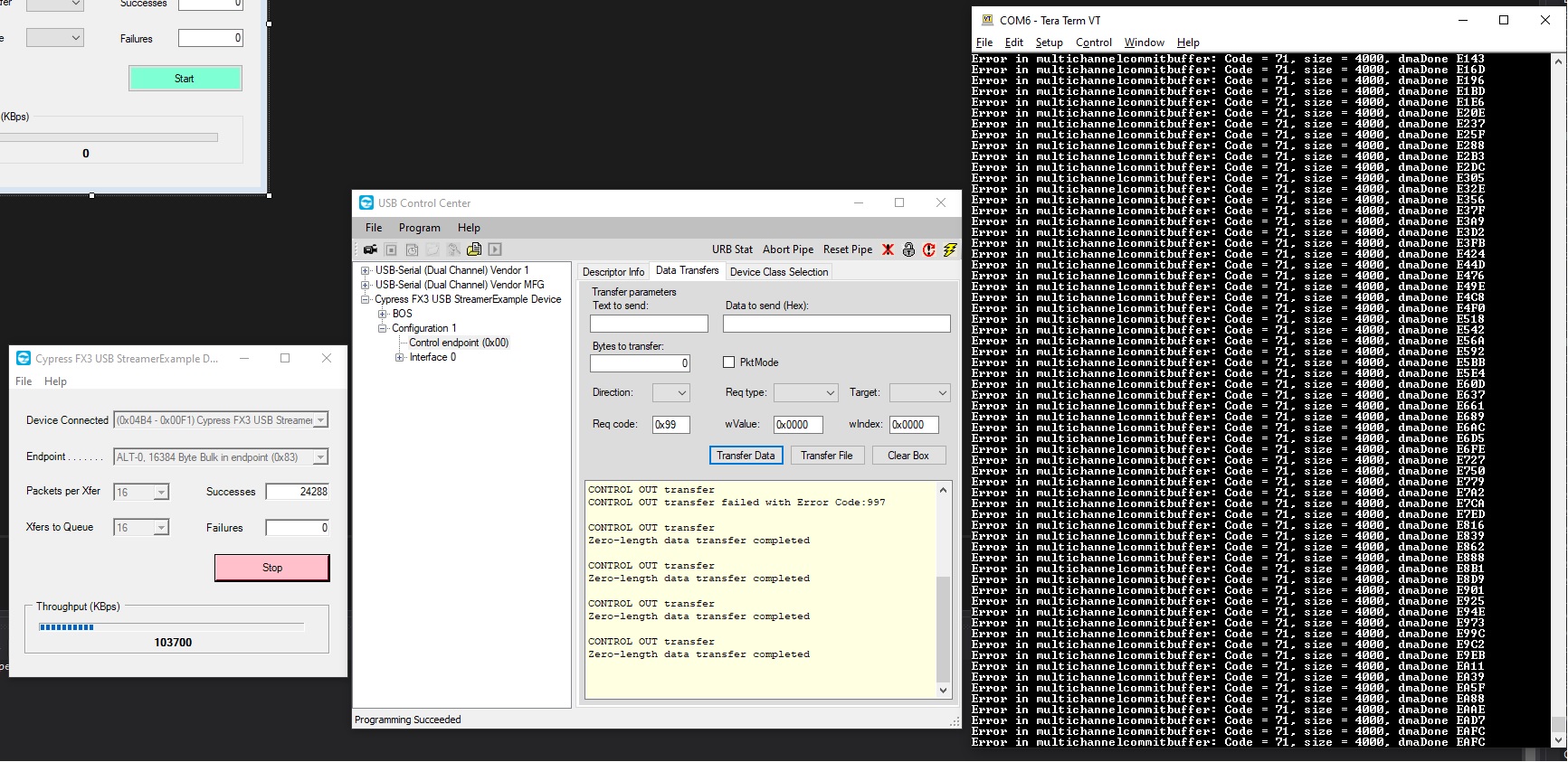
Now, when I send vendor command 0x99 and run the streamer I see lots of 0x71 errors (screenshot is attached).
The DMA and GPIF configuration remains the same, right?
Also, I tried to follow KBA218830 but I don't see the point of this when I'm using non-uvc FW.
How can I solve this error?
Thanks!
Solved! Go to Solution.
- Labels:
-
ispn:38621:1:0
-
l1:314:1:0
- Mark as New
- Bookmark
- Subscribe
- Mute
- Subscribe to RSS Feed
- Permalink
- Report Inappropriate Content
Hello,
Apologies for making a mistake in the GPIF project attached with my previous response. Please find the latest project with the fixed GPIF Project. As mentioned in my previous response, this project also works fine with streamer and provided a throughput of 54MBps.
Please find my comments for your questions n the previous response:
1. Please check the snapshot of Wireshark trace attached below:

As you can see there are lot of IN transfers of length 32791 bytes (actual data is 32764 and the remaining is wireshark header). These are the full buffers sent out from FX3. Also, you can see IN transfer of length 9127 (actual data is 9100 excluding wireshark header). This represents the partial buffers committed by FX3 to the host. As you might be knowing FX3 sends out a set of full buffers followed by one partial buffer to the host to transfer the video frame.
In the data section of full and partial buffers, first 12 bytes represents the header added by the firmware. The header is added in accordance with the UVC specification. Please find a snapshot of the data section of a full and partial buffer below:
a. For full buffer

b. For partial buffer:

You can see that the second byte of the data is 0x8c for a full buffer and 0x8e for partial buffer. If you check the second byte of all the full full buffers before a partial buffer, they will be the same. This is because the EOF buffer is to be distinguished from the full buffers.
Now, after a partial buffer with second byte as 0x8e is send out, then next set of full buffers will have the second byte as 0x8d. This will continue until the next partial buffer for which the second byte will be 0x8f. This pattern repeats until the streaming is stopped.
2. The GPIF Designer project is added along with the attached project. inside the folder fx3_uvc.cydsn.
Please let me know if you need further clarifications on this.
Best Regards,
Jayakrishna
Jayakrishna