


- Mark as New
- Bookmark
- Subscribe
- Mute
- Subscribe to RSS Feed
- Permalink
- Report Inappropriate Content
I am a beginner, I have never worked with these controllers.
I downloaded the code example for CYPD3175 and expected that fast charging support would be implemented in this example.
But when testing with QC3 and QC4, the output voltage is always 5 V (9 and 12 V are never at the output).
Please help me solve this problem.
Solved! Go to Solution.
- Mark as New
- Bookmark
- Subscribe
- Mute
- Subscribe to RSS Feed
- Permalink
- Report Inappropriate Content
Hi @Aleksey1210 ,
Thank you for posting in infineon community.
QC is enabled in the firmware which you have shared. there is no issue in that.
which hardware you are trying to communicate with this, is that supports QC 3.0 and above.
please do check follow steps and share me the result:
1. while powering -up the device, probe the D+/- lines and check the increment and decrement request from the device side and share the Waveform.
2. if you are using QC4.0, you can get the Log by using protocol analyzer. please share if you have one.
also please share the HW details which is trying to negotiate with CYPD3175.
Best Regards,
Mohamed Rahmathulla
- Mark as New
- Bookmark
- Subscribe
- Mute
- Subscribe to RSS Feed
- Permalink
- Report Inappropriate Content
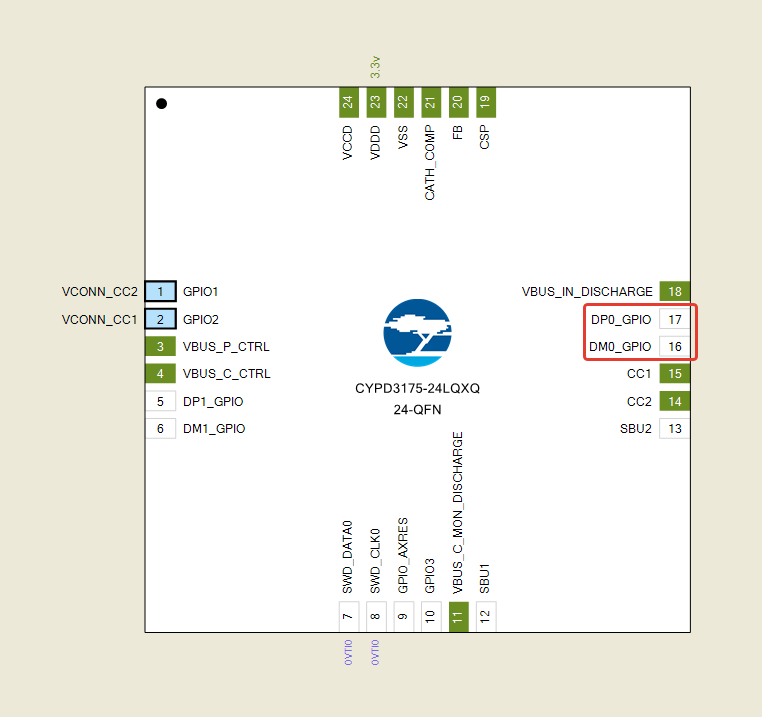
I would like to know if the two pins DP0_GPIO and DM0_GPIO are initialized. These two pins are highlighted in the picture below.
I would also like to know if it is critical that I have two pins on my circuit that are not connected anywhere. And in the diagram from 'example' these two pins are initialized. These two pins are highlighted in the picture below.
Help me on this. Thanks in advance
Best Regards,
Aleksey
@Aleksey1210 wrote:
I am a beginner, I have never worked with these controllers.
I downloaded the code example for CYPD3175 and expected that fast charging support would be implemented in this example.
But when testing with QC3 and QC4, the output voltage is always 5 V (9 and 12 V are never at the output).
Please help me solve this problem.
- Mark as New
- Bookmark
- Subscribe
- Mute
- Subscribe to RSS Feed
- Permalink
- Report Inappropriate Content
Hi @Aleksey1210 ,
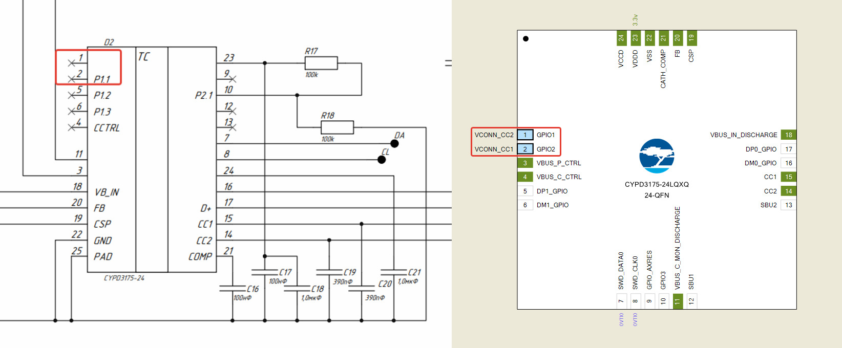
DP/DM pins are initialized in the software. even the VCONN_CC1/CC2 lines are controlling VConn supply FET,
it is need ed when you are using active cable to support EPR, Alt mode in your device. since this is for power adapter application, it is optional to control Vconn supply.
did you get any chance to check the test which i have mentioned in the earlier response??
Best regards,
Mohamed Rahmathulla
- Mark as New
- Bookmark
- Subscribe
- Mute
- Subscribe to RSS Feed
- Permalink
- Report Inappropriate Content
did you get any chance to check the test which i have mentioned in the earlier response??
no, there has not been such an opportunity to check yet
- Mark as New
- Bookmark
- Subscribe
- Mute
- Subscribe to RSS Feed
- Permalink
- Report Inappropriate Content
Check for firmware updates. Updating the firmware could potentially resolve any known issues or improve compatibility with certain devices. If possible, locate a reset button or a procedure to reset the CYPD3175 Power Adapter to its default settings. This can sometimes resolve software-related issues and restore proper charging functionality.
Regards, Jane, manager website manager
- Mark as New
- Bookmark
- Subscribe
- Mute
- Subscribe to RSS Feed
- Permalink
- Report Inappropriate Content
I would like to find out if this scheme is correct (the scheme is attached below) for the CYPD3175 Power adapter.
I would also like to know where the D+ and D- pins are initialized in the code example for CYPD3175.
I would also like to know how I can count the voltage at pins D+ and D-. Is it possible?
And if it is possible to count the voltage on D+ and D- , then I would like to know what functions will help me count the voltage on these pins.
Please help me, I reread the entire CGx_Power_SDK_API_Guide and could not find the functions for reading the voltage on D+ and D-.
Help me on this. Thanks in advance
Best Regards,
Aleksey
- Mark as New
- Bookmark
- Subscribe
- Mute
- Subscribe to RSS Feed
- Permalink
- Report Inappropriate Content
Hi @Aleksey1210 ,
bc_init(uint8_t cport) function is taken care of DP/DM resistor configuration,
there is no api to measure the DP/DM voltage but we can get the status of DP/DM lines (0 and 1).
chgb_dp_status(portnumber) is the function to check the states of D+ line
chgb_dm_status(portnumber) is the function to check the states of D+ line
if it is High, return will be True, otherwise it will be low.
Best Regards,
Mohamed Rahmathulla