

- Mark as New
- Bookmark
- Subscribe
- Mute
- Subscribe to RSS Feed
- Permalink
- Report Inappropriate Content
Hello,
I would like to generate fast sine using PWM and DMA (128kHz sine). This signal would source inverter, it would be needed complementary PWM signal, but only one of PWM out can be active during one half of sine, the second out has to be fixed low during this time (like on the below picture).
I used PWM dedicated for Motor Control, because it has got a feature to force states on the PWM output (line selection). I prepared 3 lookup tables with Period, Duty cycle and Line selection.

uint32_t period[SINE_SIZE];
uint32_t duty[SINE_SIZE];
uint32_t lineSel[SINE_SIZE];
PWM is running in Up mode, at the beggining of PWM cycle there are sent new values from lookup tables to TCPWM registers (sending is done using DMA).
period[i] -> TCPWM0_GRPx_CNTy_PERIOD_BUFF
duty[i] -> TCPWM0_GRPx_CNTy_CC0_BUFF
lineSel[i] -> TCPWM0_GRPx_CNTy_LINE_SEL_BUFF
I set up a following configuration:

An result of such configuration:

Unfortunately chops are not in accordance with defined values in lookup tables. My suspicion is that DMA transfer tooks to much time. Transfer is triggered on CC1 event, unCC1 is set to 1u.
My questions:
1. What can be a latency of DMA?
2. Is it possible to set up Trigger Multiplexer that one Trig out (TCPWM) is shared between three Trig ins of DMA (ch 8, 1 and 0)?
3. Any additional hints how to configure peripherials to achive mentioned signal?
Solved! Go to Solution.

- Mark as New
- Bookmark
- Subscribe
- Mute
- Subscribe to RSS Feed
- Permalink
- Report Inappropriate Content
Hi Jarek,
Sorry for delay, regarding your question on how much time is taken by peripheral DMA (which is being used here), following is our answer-
For Single Transfer (provided no wait state) = 14 clock cycle,
For 1D transfer, it's [12 + n*3 + m] clock cycle, where “m” total number of wait states seen by DW controller for loading/storing descriptors/data, n is no. of data elements to be transferred.
In your case, 1D transfer is used, so it will take 12 + n*3 + m clock cycle (clock is the CLK_SLOW which sources the P-DMA). 12 fixed cycle includes synchronization, detection, priority, loading descriptor etc. Each data element transfer from source to destination takes 3 cycles which is represented by n*3 in the formula, and “m” total number of wait states (if any) as seen by DW controller for loading/storing descriptors/data.
Also, I did some modifications in the she.c file (attached here), I could get the waveform (files attached) when I executed from CM0plus core. May be you can try to do the same.
Thanks,
Ashish
- Mark as New
- Bookmark
- Subscribe
- Mute
- Subscribe to RSS Feed
- Permalink
- Report Inappropriate Content
Hi,
The DMA latency is usually very low so should not affect the behavior (datasheet has not quantified this value ). But I think this could be due to priority issues. I am checking on Q2 and Q3 but can you give a detail on how are you implementing this (if you can provide the source, it'll be much better)?
Also, Can you attach a snap shot of waveform for a little longer period of time (like around 10 half sine cycles), it will help us to understand the behavior over longer time? Also, if we decrease the frequency of sine, will his still re-occur? And can you confirm if waveform is accurate (based on look-up table values), just that it's little shifted?
-Regards,
Ashish
- Mark as New
- Bookmark
- Subscribe
- Mute
- Subscribe to RSS Feed
- Permalink
- Report Inappropriate Content
Hi Ashish,
I have simplified an implemetation (it was removed one DMA channel), but still there is a problem with achiving needed signal. Please take a look.

From my observations it looks like it is not possible to update PERIOD register via DMA if the previous PERIOD value was less than 32u.
I performed two experiments:
*expected sine freq = 128kHz, not possible to achive
- decreased sine freq = 55kHz, possible to achive, but strange thing observed during Line_select switch, it looks like invert action on overlow event is performed later than line_selecet switch.
I am attaching source code and waveforms from 55kHz and 128kHz.
Function initSine() is called in main().
Regards,
Jaroslaw

- Mark as New
- Bookmark
- Subscribe
- Mute
- Subscribe to RSS Feed
- Permalink
- Report Inappropriate Content
Hi,
While trying to reproduce the scenario, I am getting some build issues. Since the project looks SDL based, can you please tell me which SDL version you uses for this project?
Thanks,
Ashish
- Mark as New
- Bookmark
- Subscribe
- Mute
- Subscribe to RSS Feed
- Permalink
- Report Inappropriate Content
Hi ,
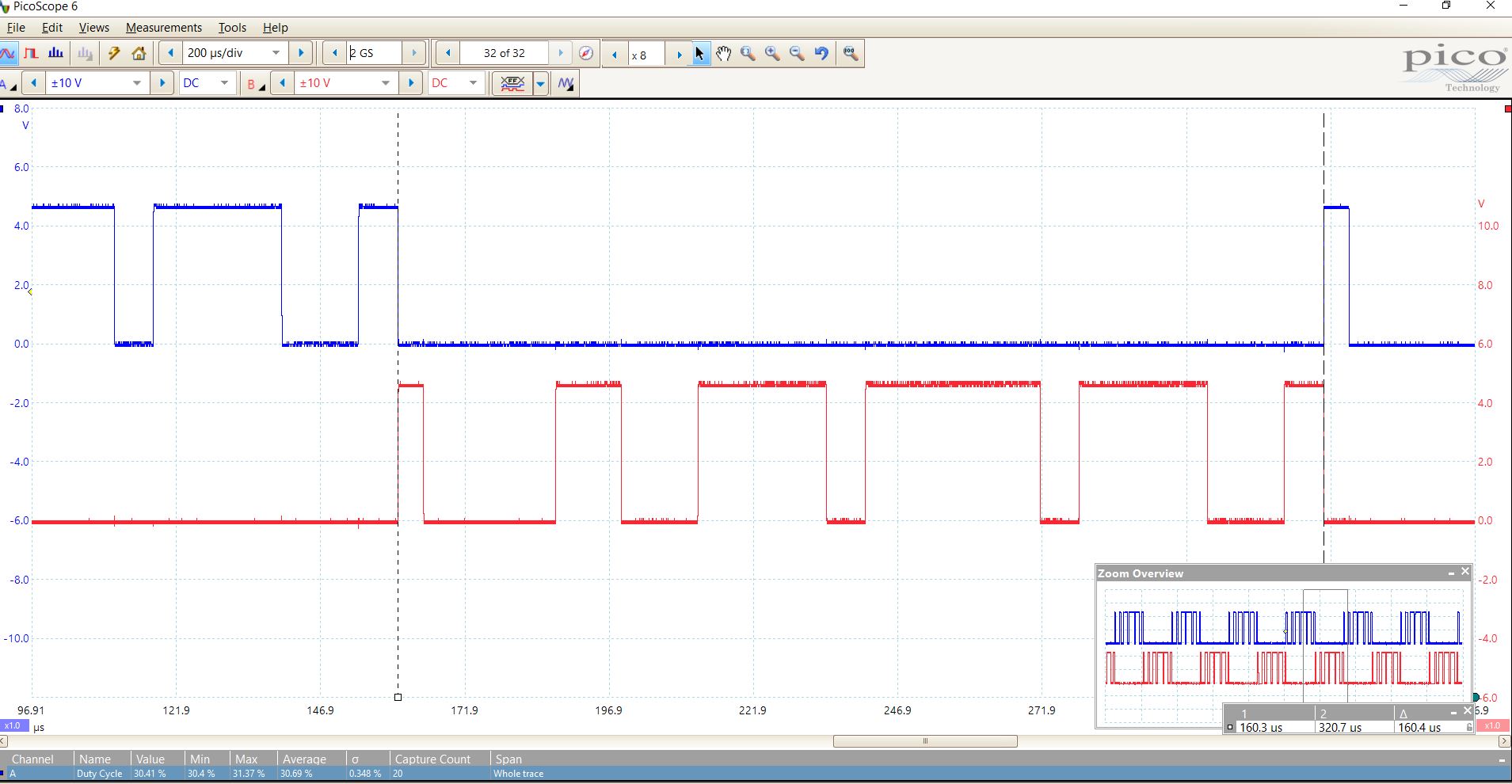
I fixed the build error by changing .killmode from CY_TCPWM_PWM_ASYNC_KILL to CY_TCPWM_PWM_STOP_ON_KILL (as CY_TCPWM_PWM_ASYNC_KILL was not defined in SDL 7.1). Also, when I observed the 55KHz on picoscope (oscilloscope), I observed that the waveform were perfectLy fine (correct me if this is not what you expect). So, in my opinion, the code is fine, probably this is the issue with either some settings with Salae analyzer or the hardware (kindly check if both the probes have identical wire length, and there is not additional capactive load etc causing delay). Alternatively you can try to change .killmode to CY_TCPWM_PWM_STOP_ON_KILL and see if this helps.
-Regards,
Ashish
- Mark as New
- Bookmark
- Subscribe
- Mute
- Subscribe to RSS Feed
- Permalink
- Report Inappropriate Content
Hi Ashish,
Thanks for involvement.
@Ashish wrote:
I observed that the waveform were perfectLy fine (correct me if this is not what you expect).
Unfortunately this not what I am expecting, please take a look at the attached images. First image shows what is wrong, second shows what is my goal.
@Ashish wrote:
Alternatively you can try to change .killmode to CY_TCPWM_PWM_STOP_ON_KILL and see if this helps.
I tried to change it, but this settings did not helped. I think that the problem is with too fast line_select switch, which is strange because it should be performed after overflow event (now it looks like it is done in half of Period which is wrong).
But the above description it is only one issue, with 55kHz sine. If you would uncomment 128kHz look up table you would see main problem which I am facing. It looks like DMA can not keep up with updating of TCPWM Period register, especially if the value of period is lower than 30 (probably it depends also from amount of DMA chanells, more chanells forces to increase value of period to achive stable signal).
I just would like to know how many cpu clock cycles is needed for DMA to prepare one transfer?
I am just guesing that it depends from amount of configured DMA chanells and chanell priority, but for simplification it can be assumed the situation from code which I attached in previous post (2 DMA chanells).
Regards,
Jarek
- Mark as New
- Bookmark
- Subscribe
- Mute
- Subscribe to RSS Feed
- Permalink
- Report Inappropriate Content
Hi Jarek,
Sorry for late reply, I am working to fix the issue in your code but it's still not very clear where is the root cause. Regarding your question, the DMA is independent of CPU, so I do not think we can measure on this parameter (cpu clock cycle), it works based on whatever frequency of clock is provided using HF clock. However, I am checking internally if we have any timing data/benchmark for DMA transfer speedz, if I get I will provide you.
Having said that, I do not think that this is timing issue/limitation, but probably some synchronization failure or DMA limitation .I am working to modify the code to achieve the desired result. I could get some result but it is still not consistent at all frequency. However, I don't think that 128KHz having issues is due to higher frequency (what you can try to do is create a constant pwm with lower period, atleast what I observed was that I could do it successfully with "periods" array value = 10U each creating square wave as shown below . It's not overlapping or appearing unusual. )

So I strongly think that issue is either with some limitation on use of dma with tcpwm block, or some configurations which need to be taken care of. I hope to soon get back to you. Meanwhile if you already got any update, kindly let me know.
Thanks,
Ashish
- Mark as New
- Bookmark
- Subscribe
- Mute
- Subscribe to RSS Feed
- Permalink
- Report Inappropriate Content
Hi Jarek,
Sorry for delay, regarding your question on how much time is taken by peripheral DMA (which is being used here), following is our answer-
For Single Transfer (provided no wait state) = 14 clock cycle,
For 1D transfer, it's [12 + n*3 + m] clock cycle, where “m” total number of wait states seen by DW controller for loading/storing descriptors/data, n is no. of data elements to be transferred.
In your case, 1D transfer is used, so it will take 12 + n*3 + m clock cycle (clock is the CLK_SLOW which sources the P-DMA). 12 fixed cycle includes synchronization, detection, priority, loading descriptor etc. Each data element transfer from source to destination takes 3 cycles which is represented by n*3 in the formula, and “m” total number of wait states (if any) as seen by DW controller for loading/storing descriptors/data.
Also, I did some modifications in the she.c file (attached here), I could get the waveform (files attached) when I executed from CM0plus core. May be you can try to do the same.
Thanks,
Ashish