


- Mark as New
- Bookmark
- Subscribe
- Mute
- Subscribe to RSS Feed
- Permalink
- Report Inappropriate Content
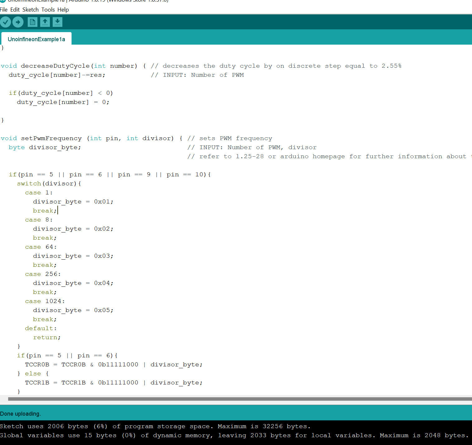
I have reloaded the sample code into an Arduino Uno. The code compiles and loads into the Arduino Uno R3.
The switches SW0, SW1, SW2, SW3 function as in the video, however S4 does not function as in the video it does not turn the BTE3050TE on/off ?


Solved! Go to Solution.
- Mark as New
- Bookmark
- Subscribe
- Mute
- Subscribe to RSS Feed
- Permalink
- Report Inappropriate Content
Hello TominMaryland,
Thank you for posting on Infineon Community.
The detailed functions of the example software (Low_Side_Switch_Shield_Arduino_Example_Software.ino) for the BTF3050TE Arduino shield can be read in page 17-18 of the user manual:
https://www.infineon.com/dgdl/Infineon-Low_Side_Switch_Shield_with_BTF3050TE_for_Arduino_Users_Manua...
Here, you can confirm the functions of the different buttons.
The definition of the button is as follows:

Therefore, we can conclude that this button does not serve as ON/OFF switch for the devices, but as a fault reset switch.
If you would like to have ON/OFF functionality in S4, you can change the following part of the code:
if(debounce(S_4)) { // S4 resets the Fault Feedback; SRP1, SRP2 and SRP3 will be pulled to ground and thus reset the Faul Feedback, afterwards the pins will be set to input again.
pinMode(SRP_1, OUTPUT); // For further information regarded the Fault Feedback, please refer to the datasheet of the BTF3050TE
pinMode(SRP_2, OUTPUT);
pinMode(SRP_3, OUTPUT);
digitalWrite(SRP_1, LOW);
digitalWrite(SRP_2, LOW);
digitalWrite(SRP_3, LOW);
for(int32_t i; i<160000;i++) {}
pinMode(SRP_1, INPUT);
pinMode(SRP_2, INPUT);
pinMode(SRP_3, INPUT);
}
To add this lines:
if(debounce(S_4)) {
duty_cycle[0] = 0;// S4 makes PWM 0 duty go to 0%
duty_cycle[1] = 0;// S4 makes PWM 1 duty go to 0%
duty_cycle[2] = 0;// S4 makes PWM 2 duty go to 0%
pinMode(SRP_1, OUTPUT);
pinMode(SRP_2, OUTPUT);
pinMode(SRP_3, OUTPUT);
digitalWrite(SRP_1, LOW);
digitalWrite(SRP_2, LOW);
digitalWrite(SRP_3, LOW);
for(int32_t i; i<160000;i++) {}
pinMode(SRP_1, INPUT);
pinMode(SRP_2, INPUT);
pinMode(SRP_3, INPUT);
}
Best regards,
Pablo
- Mark as New
- Bookmark
- Subscribe
- Mute
- Subscribe to RSS Feed
- Permalink
- Report Inappropriate Content
Hello TominMaryland,
Thank you for posting on Infineon Community.
The detailed functions of the example software (Low_Side_Switch_Shield_Arduino_Example_Software.ino) for the BTF3050TE Arduino shield can be read in page 17-18 of the user manual:
https://www.infineon.com/dgdl/Infineon-Low_Side_Switch_Shield_with_BTF3050TE_for_Arduino_Users_Manua...
Here, you can confirm the functions of the different buttons.
The definition of the button is as follows:
Therefore, we can conclude that this button does not serve as ON/OFF switch for the devices, but as a fault reset switch.
If you would like to have ON/OFF functionality in S4, you can change the following part of the code:
if(debounce(S_4)) { // S4 resets the Fault Feedback; SRP1, SRP2 and SRP3 will be pulled to ground and thus reset the Faul Feedback, afterwards the pins will be set to input again.
pinMode(SRP_1, OUTPUT); // For further information regarded the Fault Feedback, please refer to the datasheet of the BTF3050TE
pinMode(SRP_2, OUTPUT);
pinMode(SRP_3, OUTPUT);
digitalWrite(SRP_1, LOW);
digitalWrite(SRP_2, LOW);
digitalWrite(SRP_3, LOW);
for(int32_t i; i<160000;i++) {}
pinMode(SRP_1, INPUT);
pinMode(SRP_2, INPUT);
pinMode(SRP_3, INPUT);
}
To add this lines:
if(debounce(S_4)) {
duty_cycle[0] = 0;// S4 makes PWM 0 duty go to 0%
duty_cycle[1] = 0;// S4 makes PWM 1 duty go to 0%
duty_cycle[2] = 0;// S4 makes PWM 2 duty go to 0%
pinMode(SRP_1, OUTPUT);
pinMode(SRP_2, OUTPUT);
pinMode(SRP_3, OUTPUT);
digitalWrite(SRP_1, LOW);
digitalWrite(SRP_2, LOW);
digitalWrite(SRP_3, LOW);
for(int32_t i; i<160000;i++) {}
pinMode(SRP_1, INPUT);
pinMode(SRP_2, INPUT);
pinMode(SRP_3, INPUT);
}
Best regards,
Pablo
- Mark as New
- Bookmark
- Subscribe
- Mute
- Subscribe to RSS Feed
- Permalink
- Report Inappropriate Content
OK, got it!