- Mark as New
- Bookmark
- Subscribe
- Mute
- Subscribe to RSS Feed
- Permalink
- Report Inappropriate Content
I try to get the DEVSTAT status information, but when I send 4E00, I receive 40F9, which doesn't seem to be the correct data. I ran first
unlockRegisterPmic();
disableWindowWatchdogPmic(&g_tlfDevice); //disableWindowWatchdog
disableErrPinMonitorPmic(&g_tlfDevice); //disable Request ERR pin monitor
lockRegisterPmic(); and
then got the status information in a 20ms loop getCurrentStatePmic();
My EB configuration is as follows,
/* SPI channel ID */
1U,
/* Buffer Type IB/EB. */
EB,
/* SPI channel DataWidth */
(uint8)16U,
/* Default Transmit Value. */
(uint32)0x55u,
/* Data length. SpiEbMaxLength */
32U,
/* Buffer Descriptor. */
&Buffer_PBSpiChannel_1,
/* Implementation specific field referencing the channel internal state. */
&Spi_ChannelState[1],
/* Defines the first starting bit for transmission. */
MSB
/* HW unit offset, i.e.spi_n */
(uint8)3U,
/* Baud Rate (1000000 Hz) Hw configuration Parameters */
/* Packed variable for Baud Rate Configuration Parameters TQ, Q(1), A(1), B(1), C(1)
BaudRateConfig : GLOBALCON
bit 0-7: TQ
*/
(uint32)0x4U,
/* Packed variable for Delay Time Configuration params BACON
bit 0 : Last
bit 1-3: IPRE(1)
bit 4-6: IDLE(1)
bit 7-9: LPRE(1)
bit 10-12: LEAD(1)
bit 13-15: TPRE(1)
bit 16-18: TRAIL(1)
bit 19-31: Reserved
*/
(Spi_DelayConfigType)0x12492U,
/* The number of SLSO. HW channel number */
(uint8)10U,
/* Spi_ParitySelection - unused,odd.even */
SPI_ESPI_PARITY_EVEN,
/* Variable to save / restore Gpio CS pin. */
(uint16)0U, /* not used */
/* Defines the active polarity of Chip Select. */
(Spi_PolarityType)LOW,
/* The chip select */
(Spi_CsSelectionType)CS_VIA_PERIPHERAL_ENGINE,
/* This parameter defines the SPI data shift edge. */
(Spi_DataShiftEdgeType)TRAILING,
/* Enables or not the Chip Select handling functions. */
(boolean)FALSE,
/* Identify the HW SPI Hardware, i.e.spi_n */
(Spi_HWUnitType)3U,
/* defines the SPI shift clock idle level. */
(Spi_PolarityType)LOW,
/* Timing between clock and chip select(i.e. LEAD time) in ns */
(uint32)200U,
and my sending and receiving functions are as follows.
Can someone help me look at it? Thank you very much
Solved! Go to Solution.
- Mark as New
- Bookmark
- Subscribe
- Mute
- Subscribe to RSS Feed
- Permalink
- Report Inappropriate Content
Hello,
I hope you are using Aurix MCU.
Can you please try with the below example code?
https://github.com/Infineon/AURIX_code_examples/tree/master/code_examples/SPI_TLF_1_KIT_TC397_TFT
One more question, what is meant by " mcu to msb" in your comment?
Regards
Vishnu
- Mark as New
- Bookmark
- Subscribe
- Mute
- Subscribe to RSS Feed
- Permalink
- Report Inappropriate Content
Hello,
Are you able to keep the safe state and ROT pin to "High"?
I just want to check your initial configuration is working fine with this.
As you said, the read data (SDO) is not correct.
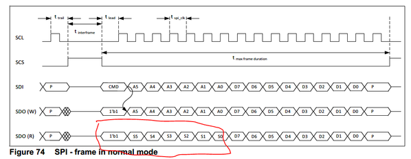
The read operation is not following the below format.
Can you please send the SPI log in .csv format?
Regards
Vishnu
- Mark as New
- Bookmark
- Subscribe
- Mute
- Subscribe to RSS Feed
- Permalink
- Report Inappropriate Content
Q1:We have canceled the watchdog function in other ways, and the ROT is always high
Q2: Now I turn off the automatic verification of hardware, and write a odd verification function and add it to the last bit.
Now run the unlock function and send 0x8756, 0x87DE, 0x86AD, 0x8625. All received data are 8001. Sending 4E00 is also 8001. Shouldn't cmd bit 1 be the way of writing? Shouldn't the returned data be the same as the data you sent.
This address bit is completely correct,
Is it correct to set the mcu to msb?
Q3: I can find "the SPI log"😭
- Mark as New
- Bookmark
- Subscribe
- Mute
- Subscribe to RSS Feed
- Permalink
- Report Inappropriate Content
Hello,
I hope you are using Aurix MCU.
Can you please try with the below example code?
https://github.com/Infineon/AURIX_code_examples/tree/master/code_examples/SPI_TLF_1_KIT_TC397_TFT
One more question, what is meant by " mcu to msb" in your comment?
Regards
Vishnu


