


- Mark as New
- Bookmark
- Subscribe
- Mute
- Subscribe to RSS Feed
- Permalink
- Report Inappropriate Content
Hello,
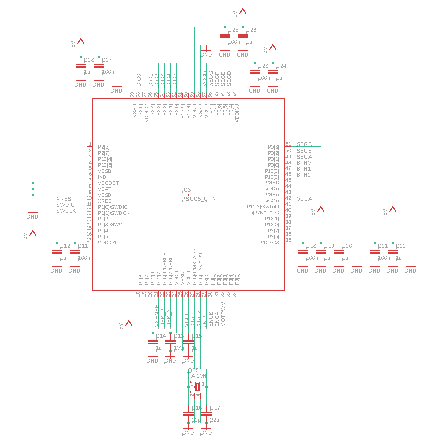
I have severe problems getting USB peripheral of PSoC5 to work. Attached are schematics and layout of my board design.
Whatever I burn into MCU, nothing works...my application, any changes to it, USB-UART CDC example. This I believe rules out software problems. Device simply cannot be detected by computer at all. If I hard-reset USB data-line by applying external pull-up, unknown device is detected.
I have replaced MCU, ESD protection IC, series resistors, no change. I have sacrificed Cypress USB-BLE dongle's MCU, before unsoldering it was working fine. After moving to my board, it does not work.
If I disconnect computer, and burn firmware outputting clock on USB data-lines, I do not see clean square-wave (impedance mismatch to scope probe?), but I can definitively see correct frequency.
Now my question, what is happening there? I need this board to work correctly ASAP, but I am running out of ideas what to check.
Thanks in advance,
Stanislav
Solved! Go to Solution.
- Labels:
-
PSOC5 LP MCU
- Tags:
- usb
- Mark as New
- Bookmark
- Subscribe
- Mute
- Subscribe to RSS Feed
- Permalink
- Report Inappropriate Content
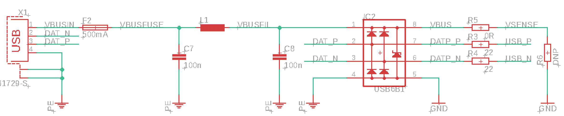
Okay, solved. I have got 22MOhm resistors instead of 22Ohm. And additionally a faulty USB connector.
Lesson: Don't think of over-complicated causes and solutions. Sometimes the most simple occurs.
- Mark as New
- Bookmark
- Subscribe
- Mute
- Subscribe to RSS Feed
- Permalink
- Report Inappropriate Content
Hello.
Did you check if the USB fuse is still good?
If the USB surge protection device is installed backwards, it will blow the fuse (and possible damage to USB protection device). Check its orientation. You could remove the USB surge protection device for the time being.
"burn firmware outputting clock on USB data-lines" I'm not sure what you meant by this.
I'm not aware that you can route a clock signal to a USB pin.
BTW, USB signals are not square waves. At best, they are rounded impulses.
Does your project (or the USB example) compile without any errors?
If yes, is the Flash programming successful?
BTW, you should have a pull-up resistor on XRES. Yes, the documentation says PSoC has an internal pull-up, but I find it to be unreliable.
Have you tried a simple project, toggle a GPIO pin to observe it this works?
- Mark as New
- Bookmark
- Subscribe
- Mute
- Subscribe to RSS Feed
- Permalink
- Report Inappropriate Content
Hello,
I do not have problems with VBUS sense, I only have problems with communication itself.
I did manage to output clock on these pins - not sure what part are you talking about, on mine they are standard gpio P15[6] and P15[7].
Also, no problems with compilation/flashing. I can successfully burn my firmware, anything but USB communication is operational.
Stanislav
- Mark as New
- Bookmark
- Subscribe
- Mute
- Subscribe to RSS Feed
- Permalink
- Report Inappropriate Content
Hi.
We're talking about the same 5LP. I wasn't aware a clock could be routed to the USB pins, I wasn't implying it couldn't.
Thanks for clarifying "nothing works" means everything works except USB communication.
I run USBFS component configured as MIDI and it simply runs (on KIT-059). I didn't even have to install the inf.
Sounds like a driver issue for your setup. Beyond my knowledge.
Good luck with your project. Hopefully Infineon will come up with a solution for you.
edit: I routed a clock to P15[6] and the output was a perfect square wave. No overshoot, no rounding, 5V amplitude, correct frequency, nothing weird. The schematic difference is, KIT-059 has no surge protection device on those signals.
- Mark as New
- Bookmark
- Subscribe
- Mute
- Subscribe to RSS Feed
- Permalink
- Report Inappropriate Content
Okay, solved. I have got 22MOhm resistors instead of 22Ohm. And additionally a faulty USB connector.
Lesson: Don't think of over-complicated causes and solutions. Sometimes the most simple occurs.
- Mark as New
- Bookmark
- Subscribe
- Mute
- Subscribe to RSS Feed
- Permalink
- Report Inappropriate Content
Good to hear you got it working and you were good enough to post the solution. So many people leave us "up in the air hanging".
Yeah, wrong resistor value will do it.
Just as bad as the diode I installed and the 'band' marking cathode was at the wrong end (manufacturers defect). Took a while to figure that one out too.
BTW, I normally route the pcb tracks right under/through the surge protection device (essentially, in parallel with the device internal connections). I know the datasheet shows the internal connections, but not all devices do this. I was beginning to suspect the USB6B1 device.
I hope the rest of your project goes smoothly.