


- Mark as New
- Bookmark
- Subscribe
- Mute
- Subscribe to RSS Feed
- Permalink
- Report Inappropriate Content
Hello,
im receive some data (RX) via UART :
1. convert it (atoi()) into a Integer,
2. conver it (itoa()) into a String and sent it (TX) via UART.
Meanwhile, reading 2 voltages (dualadc) and output (dac8) one voltage.
Problem -> If i comment-out all ADC and DAC Code, the UART Communication works fine. But with all User-Moduls + miniCode the UART Communication is faulty (irregular).
:: What can i do?
Settings:
Global Settings = 24Mhz, (Vdd/2)+/-(Vdd/2), SC On/Ref High
UART = 9600, Sync to SysClk,
DUALADC = 8 Bit, CalcTime 45, DUALADC_HIGHPOWER, PGA_1_HIGHPOWER, PGA_2_HIGHPOWER,
DAC = DAC8_HIGHPOWER
Thanks for your reply.
- Labels:
-
PSoC 1
- Mark as New
- Bookmark
- Subscribe
- Mute
- Subscribe to RSS Feed
- Permalink
- Report Inappropriate Content
"smells" a bit like stack fault or overwritten variables.
Only thing I can see so far (well documented and clean code!!!) is the size of the rx buffer which is currently set to 10 bytes.
1 command, 2 separators, 2 params, 1 zero byte that is 4 bytes left for 2 params. Seems a bit low imho.
Bob
- Mark as New
- Bookmark
- Subscribe
- Mute
- Subscribe to RSS Feed
- Permalink
- Report Inappropriate Content
At second thought... There are more modern chips (which already have got a BLE radio included which could make your design smaller and easier. Ever looked at those PSoC4 chips with a BLE 4.1 radio in a simple module ~10x10x 1.8mm.
Bob
- Mark as New
- Bookmark
- Subscribe
- Mute
- Subscribe to RSS Feed
- Permalink
- Report Inappropriate Content
Thanks for your fast help!
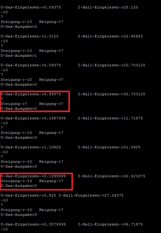
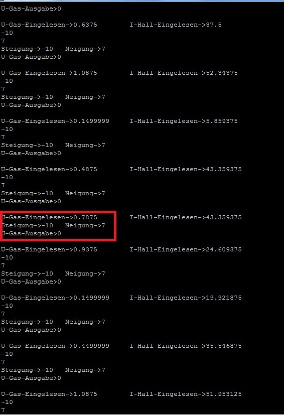
I increased the RX-Buffer, but same Problem (see Pics).
My Approach:
1. Check the TX-Data from Device 1 with another UART-PC-Transmitter = Device 1 sends all data correct.
2. Check the TX-Data from Device 2 (.zip) with another UART-PC-Transmitter = Device 2 TX Communication is faulty (irregular).
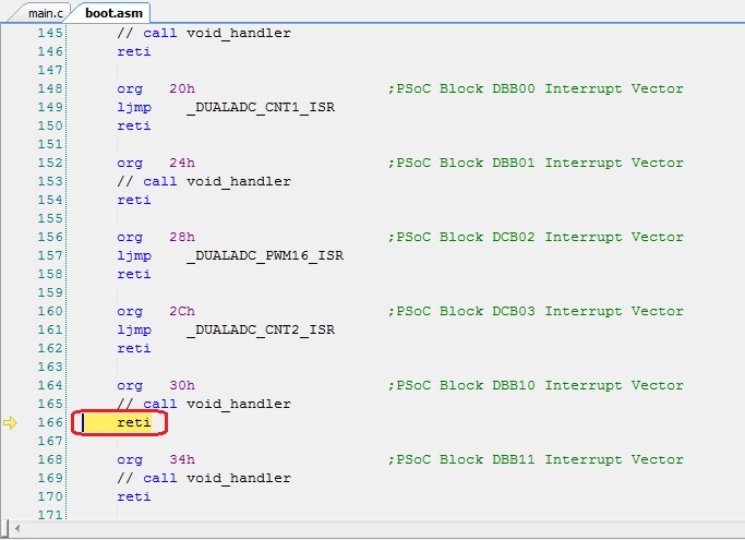
3. Read AN15576 and the debugger stopped the code on "boot.asm / org 30h, reti(PSoC Block DBB10)".
What does this mean?
One another thing, im searching a Prototyping Kit with included Bluetooth Modul and i can only find the PSoC 4 Pioneer Kit. Does Cypress sell another Prototyping Kit + Bluetooth (not separated).
Thanks for your reply!
- Mark as New
- Bookmark
- Subscribe
- Mute
- Subscribe to RSS Feed
- Permalink
- Report Inappropriate Content
Have a look at this kit.
You obviously have got an ICE-Cube, did you monitor the stack?
And check the status for zero (or pvar for non-zero) after ftoa()
Bob
- Mark as New
- Bookmark
- Subscribe
- Mute
- Subscribe to RSS Feed
- Permalink
- Report Inappropriate Content
... and give this a try:
csprintf(Buffer,"I-Hall-Eingelesen->%f\n\r",I_Hall_Neu);
UART_PutString(Buffer);
You'll need
#include "stdio.h>
char Buffer[40];
Bob
- Mark as New
- Bookmark
- Subscribe
- Mute
- Subscribe to RSS Feed
- Permalink
- Report Inappropriate Content
Thanks for your help, but csprintf dont work with floats --> Uart Output is black screen (with %d for decimal = it works)
One other Question: how can i convert negative floats (e.g. -2.344)to string, because ftoa is characterised = /* |input| > 2147483520 *//* |input| < 0.0000001 */ = Out of Range
- Mark as New
- Bookmark
- Subscribe
- Mute
- Subscribe to RSS Feed
- Permalink
- Report Inappropriate Content
You have to do that yourself, when the number is negative change to a positive and prepend the result with a minus sign.
Bob
- Mark as New
- Bookmark
- Subscribe
- Mute
- Subscribe to RSS Feed
- Permalink
- Report Inappropriate Content
I did exactly what you say "
... and give this a try:
csprintf(Buffer,"I-Hall-Eingelesen->%f\n\r",I_Hall_Neu);
UART_PutString(Buffer);
You'll need
#include "stdio.h>
char Buffer[40];"
with a new Project, but no Uart output. What is wrong? (I reinstalled Psoc Designer 5.4 SP1)

- Mark as New
- Bookmark
- Subscribe
- Mute
- Subscribe to RSS Feed
- Permalink
- Report Inappropriate Content
I cannot even see your welcomeScreen(). This should work.
Bob
- Mark as New
- Bookmark
- Subscribe
- Mute
- Subscribe to RSS Feed
- Permalink
- Report Inappropriate Content
Sorry it didn't work.

- Mark as New
- Bookmark
- Subscribe
- Mute
- Subscribe to RSS Feed
- Permalink
- Report Inappropriate Content
Hmmm...., seems as if the printf() family not correctly implemented using floats for PSoC1.
Bob
- Mark as New
- Bookmark
- Subscribe
- Mute
- Subscribe to RSS Feed
- Permalink
- Report Inappropriate Content
Can I do Anything?
By the way, the Uart Output from Device 2 to Device 1 was lost because the transmission was to fast...
I found a Sting to Float Function + negative numbers + decimal place definition
void ftoaNew(char *buffer, float var, int precision)
{
long wholePart = (long) var;
char *endOfString= buffer;
float fraction;
// Deposit the whole part of the number.
itoa(buffer,wholePart,10);
// Now work on the faction if we need one.
if (precision > 0) {
// We do, so locate the end of the string and insert
// a decimal point.
while (*endOfString != '\0') endOfString++; //im buffer von itoa
*endOfString++ = '.';
// Now work on the fraction, be sure to turn any negative
// values positive.
if (var < 0) {
var *= -1;
wholePart *= -1;
}
fraction = var - wholePart; //Trennung von Nachkommastellen und Vorkomma
while (precision > 0) {
// Multipleby ten and pull out the digit.
fraction *= 10;
wholePart = (long) fraction;
*endOfString++ = '0' + wholePart; // ASCII Table z.B. 5 => '0' = 48 + 5 = 53 = '5'
// Update the fraction and move on to the
// next digit.
fraction -= wholePart; // nächste Nachkommastelle
precision--;
}
// Terminate the string.
*endOfString = '\0';
}
}
- Mark as New
- Bookmark
- Subscribe
- Mute
- Subscribe to RSS Feed
- Permalink
- Report Inappropriate Content
Yes, you should use that conversion.
Bob
- Mark as New
- Bookmark
- Subscribe
- Mute
- Subscribe to RSS Feed
- Permalink
- Report Inappropriate Content
One little Question:
If i use 1 DUALADC on PIN 0_0 & 0_1 and 1 DAC8 on PIN 0_5, can i set PIN 0_3 with "PRT0DR |= 0b1000;" high (for a LED) or should i use a shadow Reg. ?
- Mark as New
- Bookmark
- Subscribe
- Mute
- Subscribe to RSS Feed
- Permalink
- Report Inappropriate Content
Your pin usage of P0 is analog, so you probably do not need a shadow register, but I would suggest you to use one. No problems when project gets expanded.
Bob
- Mark as New
- Bookmark
- Subscribe
- Mute
- Subscribe to RSS Feed
- Permalink
- Report Inappropriate Content
Thanks for your Help.
Another Question: I found "StripLights" (http://www.cypress.com/forum/psoc-community-components/neopixel-ws281112-component) for PSoC4. Can i find anything like that for PSoC1?
- Mark as New
- Bookmark
- Subscribe
- Mute
- Subscribe to RSS Feed
- Permalink
- Report Inappropriate Content
You are living in (good old) Germany, so access to US products is easy. Have a look into the distributor's websites as Mouser or Future electronics (best experiences) for Cypress prototyping kits. Prices are comparably low, you even can get a (very powerful) PSoC5 prototyping kit for $10. I do not use PSoC1 for new designs (too expensive when calculating chip, time and equipment needed), but PSoC4s and 5s.
Bob
- Mark as New
- Bookmark
- Subscribe
- Mute
- Subscribe to RSS Feed
- Permalink
- Report Inappropriate Content
1. On the Datasheet "CY8C58LP Family Datasheet" which is on "cy8ckit-059-psoc-5-prototyping-kit", i found a CAN Interface. What
additional device (plz cheap) should i buy?
2. On the Psoc5lp prototyping kit is 2 pins labeled for uart and 2 pins for I2C. What is with SPI and can i choose e.g. Pin 0_1 & P 0_2 for added UART Communication?
I never worked with the psoc creator ...
Thanks
I will order "http://www.cypress.com/documentation/development-kitsboards/cy8ckit-059-psoc-5lp-prototyping-kit-onb...
- Mark as New
- Bookmark
- Subscribe
- Mute
- Subscribe to RSS Feed
- Permalink
- Report Inappropriate Content
PSoC5s are able to route (nearly) every output to any pin. Exception is the USB interface and some dedicated pins.
Download and install Creator asap! Download and install the Kit files! Watch the videos to see how to work with Creator. Will take you a day. Play with the example projects. You can start all this today before your hardware arrives.
CAN controller is imho not quite easy to program, at first you will need another CAN devive which you CAN can connect your kit to. You will need CAN-bus drivers to provide the required interface. When you have got two PSoC CAN interfaces you may during the development phase connect them directly without the drivers.
Bob
- Mark as New
- Bookmark
- Subscribe
- Mute
- Subscribe to RSS Feed
- Permalink
- Report Inappropriate Content
Cool, lets start it 🙂
To the CAN Bus, in the past i worked with different Fieldbusses e.g. https://www.br-automation.com/de-de/produkte/steuerungssysteme/x20-system/bus-controller/x20bc0053/ , CANopen, DeviceNet, Profibus,.... and it was always similar: adjust BUS Parameters, depend on it and speak on the BUS. CAN i do it equal with a PSoC5 Developement Kit or need i a level amplifier or any extra Hardware? With the FDT/DTM Driver you have always the same surface....
Thx for your reply
- Mark as New
- Bookmark
- Subscribe
- Mute
- Subscribe to RSS Feed
- Permalink
- Report Inappropriate Content
Since CAN line is a two-wire differential IO you will need an interface chip like this one.
Could be too difficult for a newbie to integrate the driver using the PSoC5 internal OpAmps.
Bob
- Mark as New
- Bookmark
- Subscribe
- Mute
- Subscribe to RSS Feed
- Permalink
- Report Inappropriate Content
Cool, but i dont need this interface chip, if i use 3 x PSoC 5 development kits and they are communicate over CAN. Is that right?
- Mark as New
- Bookmark
- Subscribe
- Mute
- Subscribe to RSS Feed
- Permalink
- Report Inappropriate Content
Should work, I never tried that. Just connect the Rx and Tx crosswise.
Bob
- Mark as New
- Bookmark
- Subscribe
- Mute
- Subscribe to RSS Feed
- Permalink
- Report Inappropriate Content
I have some basic Question:
1.PSoC fundamental Advantage is that i can not only simulate OpAmplifier, LogicBlocks !?
2.Thus i can create e.g. this CAN-IC (Above) within the PSoC-Controller!?
3.Thus i need fundamental Elec. Knowlegde, without that i can use every standard uC, can you recommend a German Book/PDF, because the i have no Ideas what can all i do and for what. The PSoC AN are very good, but you need first the Idea and then you can learn from the PSoC AN..
- Mark as New
- Bookmark
- Subscribe
- Mute
- Subscribe to RSS Feed
- Permalink
- Report Inappropriate Content
i can not only simulate OpAmplifier, LogicBlocks As a matter of fact, it is not a simulation. The components as OpAmp, SCBs UDBs are really there.
i can create e.g. this CAN-IC (Above) within the PSoC-Controller Yes, quite right. What you get is an agglomeration of internal hardware and a bunch of software. APIs to access the underlying hardware, all made ready by Cypress and documented for you on a silver tablet 😉
Thus i need fundamental Elec. Knowlegde Yes, fundamental. I have seen Mark Sounders from Cypress programming a model car to follow a black line on white paper. All was done in software. Then he changed the project and realized the whole problem in pure hardware. It is THE advantage that you can get solutions that fit to your style and knowledge. How much C-code and how much hardware you will use just depends on you.
I haven't got a recomendation for a book, but I would suggest you to ask in Amazon -> Books for PSoC and decide for yourself. The book written by Dave van Ess is very basic and really deals with bits, so you can skip that.
Bob
- Mark as New
- Bookmark
- Subscribe
- Mute
- Subscribe to RSS Feed
- Permalink
- Report Inappropriate Content
One little Question to the PSoC Designer (PSoC1). Does a long, int, char wrap around automatic, if i increment it to the max (wraps around from INT_MAX to INT_MIN )?
Thanks Bob
- Mark as New
- Bookmark
- Subscribe
- Mute
- Subscribe to RSS Feed
- Permalink
- Report Inappropriate Content
- Mark as New
- Bookmark
- Subscribe
- Mute
- Subscribe to RSS Feed
- Permalink
- Report Inappropriate Content
Thats cool, thank you !
To the UART / PSoC 1, if i that the "Global Resources-Ref Mux to VDD/2-+VDD/2" is the TTL-Pegel 3,3V or 5V?
- Mark as New
- Bookmark
- Subscribe
- Mute
- Subscribe to RSS Feed
- Permalink
- Report Inappropriate Content
Afaik does the refmux value have no influence in the level on input pins.
Bob
- Mark as New
- Bookmark
- Subscribe
- Mute
- Subscribe to RSS Feed
- Permalink
- Report Inappropriate Content
Thank you, so it should be 5V TTL-Level!?
- Mark as New
- Bookmark
- Subscribe
- Mute
- Subscribe to RSS Feed
- Permalink
- Report Inappropriate Content
I measured it with an oscilloscope --> 3,3V Level