


- Mark as New
- Bookmark
- Subscribe
- Mute
- Subscribe to RSS Feed
- Permalink
- Report Inappropriate Content
I am developing one device where i need to turn on LED when signal become high and turn off LED when signal become low .during the LED blinking i have to control the LED light intensity through push up/down botton or (through capsence).
i have attached a jpg of my input signal which is for turn OFF and ON 10 times in 1 sec .
Solved! Go to Solution.
- Labels:
-
PSoC 1
- Mark as New
- Bookmark
- Subscribe
- Mute
- Subscribe to RSS Feed
- Permalink
- Report Inappropriate Content
Then I would consider using a comparator (simplest) to detect level
and in turn in code use that to enable a PWM. When PWM active
use its compare value to control duty cycle, hence brightness of
LED.
Set PWM period so that it is ~ 100 Hz or more to avoid flicker in LED.
Note timer would work here as well. Or SSDM module, it will result in
better EMI reduction.
Regards, Dana.
- Mark as New
- Bookmark
- Subscribe
- Mute
- Subscribe to RSS Feed
- Permalink
- Report Inappropriate Content
- Mark as New
- Bookmark
- Subscribe
- Mute
- Subscribe to RSS Feed
- Permalink
- Report Inappropriate Content
Describe the input signal, its source if possible, is it AC, DC,
freq if AC.
What property of the signal turns LED on or off ? Paek, average, RMS, period.....?
Your input signal pic not showing up in my browsers (Firefox, Chrome).
Regards, Dana.
- Mark as New
- Bookmark
- Subscribe
- Mute
- Subscribe to RSS Feed
- Permalink
- Report Inappropriate Content
i am using chrome .... already attached one file ....you can download .
led should turn on when signal at zero (low) leval .
time duration for led turn on and off--
turn on =0.025 sec
turn off=0.045 sec
Vpp =2.5v
- Mark as New
- Bookmark
- Subscribe
- Mute
- Subscribe to RSS Feed
- Permalink
- Report Inappropriate Content
Then I would consider using a comparator (simplest) to detect level
and in turn in code use that to enable a PWM. When PWM active
use its compare value to control duty cycle, hence brightness of
LED.
Set PWM period so that it is ~ 100 Hz or more to avoid flicker in LED.
Note timer would work here as well. Or SSDM module, it will result in
better EMI reduction.
Regards, Dana.
- Mark as New
- Bookmark
- Subscribe
- Mute
- Subscribe to RSS Feed
- Permalink
- Report Inappropriate Content
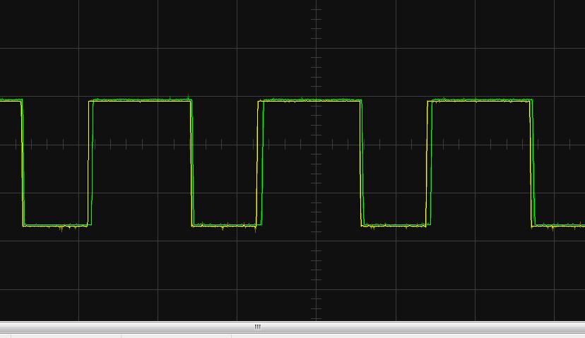
Hi i am using COMPA comparator ... in below given pics yellow one is my filter output and green one is my caomparator output.
but comparator output (green) is flickering too much ...
for elimination of flicker i am using RC integrator .after that i am able to get this out put
but actually i want to eliminate this flicker noise at my out put .... how i can get this out put as i mention below ...
plzz help me to find out the out put tell me the best way to remove fliker at my out put .....
- Mark as New
- Bookmark
- Subscribe
- Mute
- Subscribe to RSS Feed
- Permalink
- Report Inappropriate Content
- Mark as New
- Bookmark
- Subscribe
- Mute
- Subscribe to RSS Feed
- Permalink
- Report Inappropriate Content
Best for controlling LED intensity is a SSDM component for PSoC1. Use a linear function, input is your button up/down counter, output is the "density" value for SSDM.
Bob
- Mark as New
- Bookmark
- Subscribe
- Mute
- Subscribe to RSS Feed
- Permalink
- Report Inappropriate Content
Dear Bob
i trying to control LED through DAC ... but m not able geting the result from DAC even basic code is not working ... m taking VC1 =clk/2 , and output pin is strong ...
CODE-
DAC6_1_Start(DAC6_1_HIGHPOWER);
while(1)
if(bDACValue == 0)
{
bDACValue = DAC_MAX; // Reset DAC value to the max if it reached zero
}
DAC6_1_WriteStall(bDACValue--); // Write value to DAC and decrement
- Mark as New
- Bookmark
- Subscribe
- Mute
- Subscribe to RSS Feed
- Permalink
- Report Inappropriate Content
If you are using a VDAC driving thru output buffer you will have a
very non linear brightness vs V result in LED. Thats why you should
use SSDM or PWM. Or convert VDAC to IDAC., which is not a good
solution.
www.phys.uconn.edu/~hamilton/phys258/N/led.pdf
This shows I thru LED which is directly proportional to LED brightness.
So use of VDAC very limiting.
Regarding your code loop, you very rapidly go from max IDAC to 0, there
is no delay, and repeat. So average VDAC is 1/2 Vdd which probably does
not push much I thru LED. In any event use of IDAC NOT recommended.
Regards, Dana.
- Mark as New
- Bookmark
- Subscribe
- Mute
- Subscribe to RSS Feed
- Permalink
- Report Inappropriate Content
Hi dana thanks
but i want to know why you do not want to recommended IDAC for event use ... will you elaborate this ...
- Mark as New
- Bookmark
- Subscribe
- Mute
- Subscribe to RSS Feed
- Permalink
- Report Inappropriate Content
Where are you going to take an IDAC from when driving a non-linear LED?
Bob
- Mark as New
- Bookmark
- Subscribe
- Mute
- Subscribe to RSS Feed
- Permalink
- Report Inappropriate Content
i have already one output m showing below (green one) ... LED also blinking according to rectanguler pulse ......one side of LED anode pin is connected through rectaguler pulse (which is providing ground) and otherside is connected through Vcc ... i just want to control the (Vcc) voltage or current of cathode side of LED pin by pressing up/down push botton ... i don't know which mathod is good ... when rectanguler pulse providing ground....
- Mark as New
- Bookmark
- Subscribe
- Mute
- Subscribe to RSS Feed
- Permalink
- Report Inappropriate Content
As alredy said: use the SSDM module @100kHz and controll the density by API when up/dwn buttons pushed.
Bob
- Mark as New
- Bookmark
- Subscribe
- Mute
- Subscribe to RSS Feed
- Permalink
- Report Inappropriate Content
The reasons you cannot use IDAC are -
1) Max IDAC output is ~ 600 uA, insufficient to run most hi efficiency LEDs
to an adequate brightness level.
2) Your Vcc is 3.3V, The complience range of the IDAC is 0 - 2.3 V in that case.
Most hi bright LEDs, depending on color, have Vth exceeding 2V, in some case
3V. This means you could barely turn on LED because of Vth. And LED to LED
variation is horrible, so of the ones you could light up you woud have large
brightness variation from one LED to another.
3) A PWM works because you can control the width of the pulse, or duty cycle,
of the pulse. That in turn means the average effective DC value of the wavefom
can vary from 0 - 100% at the output. If the period of the PWM is ~ > 60 Hz you
will not see any flicker. Human eye acts as an integrator, so if you pass a pulse
of light to it it will integrate that pulse into an effective average light intensity.
4) The SSDM changes density of pusle train effective doing the same thing as
the PWM.
Use the SSDM or a PWM.....
Regards, Dana