

- Mark as New
- Bookmark
- Subscribe
- Mute
- Subscribe to RSS Feed
- Permalink
- Report Inappropriate Content
I am using a 5LP device in a product that is being tested for FCC and CE certification. The response is slightly out of limits at 80MHz and I suspect this is the controller. I need to reduce Radiated emission by 2uV at 80MHz.
The controller is being run at 3.3V.
Are there some relatively easy to implement techniques to lower the RE? (ie. A clock parameter change or something I would turn off)?
The hardware has short traces, plenty of decoupling close by the controller and laid out with large ground plane with lots of vias stitching top and bottom layers. (it is a 2 layer PCB, 1.6m thick with 1oz copper).
My project uses a 1ms timer, SPI, RS485 and a generated 125 kHz Square wave signal from PWM.
Thanks
Solved! Go to Solution.
- Labels:
-
PSoC 5LP
- Mark as New
- Bookmark
- Subscribe
- Mute
- Subscribe to RSS Feed
- Permalink
- Report Inappropriate Content
Well, when thinking of frequencies you ought to keep in mind that the rise and fall (no, not the house of Usher 😉 of a signal introduces very high frequencies.
As you probably now you can compose (theoretically) any waveform by summing sines of different frequencies. For a square wave you will need high frequencies to accomplish the sudden changes. Reducing any slew rate will decrease that frequencies.
If it is not too complicated for you to measure, give it at least a try.
I'm not quite used to measuring 80MHz radiation, but can you use a probe that picks up that noise to see from where it is emitted?
Bob
- Mark as New
- Bookmark
- Subscribe
- Mute
- Subscribe to RSS Feed
- Permalink
- Report Inappropriate Content
Is the PSoC running at 80MHz? IMO or external clock? Any Crystal?
Are any signals leaving the chip? Can those pins be configured with "slow slew rate" (at pins output configuration) which will reduce straying rf.
Bob

- Mark as New
- Bookmark
- Subscribe
- Mute
- Subscribe to RSS Feed
- Permalink
- Report Inappropriate Content
- Mark as New
- Bookmark
- Subscribe
- Mute
- Subscribe to RSS Feed
- Permalink
- Report Inappropriate Content
RE tests show response on first test at 80.644 MHz and second test at 79.243MHz.
I am not sure if the micro is the issue but the other clock sources on PCb are all much lower (115k RS485, 250KHz switching PSU, 125KKz and SPI bus).
If not the controller radiated emissions then maybe harmonic of the SPI?
- Mark as New
- Bookmark
- Subscribe
- Mute
- Subscribe to RSS Feed
- Permalink
- Report Inappropriate Content
So one signal leaving your board is the UART. Are you using a level converter on hte board as Max232?
Can you reduce rf stray by setting the Tx pin to slow slew rate while keeping your rs485 functional?
Bob
- Mark as New
- Bookmark
- Subscribe
- Mute
- Subscribe to RSS Feed
- Permalink
- Report Inappropriate Content
I am using equivalent of Max485 for level shifting.
The frequency of the 485 (around 65khz) is miles away from the 80MHz signal being emitted (1230th harmonic)
- Mark as New
- Bookmark
- Subscribe
- Mute
- Subscribe to RSS Feed
- Permalink
- Report Inappropriate Content
Well, when thinking of frequencies you ought to keep in mind that the rise and fall (no, not the house of Usher 😉 of a signal introduces very high frequencies.
As you probably now you can compose (theoretically) any waveform by summing sines of different frequencies. For a square wave you will need high frequencies to accomplish the sudden changes. Reducing any slew rate will decrease that frequencies.
If it is not too complicated for you to measure, give it at least a try.
I'm not quite used to measuring 80MHz radiation, but can you use a probe that picks up that noise to see from where it is emitted?
Bob
- Mark as New
- Bookmark
- Subscribe
- Mute
- Subscribe to RSS Feed
- Permalink
- Report Inappropriate Content
Bob,
Thanks again for your help. I agree, it could be rise times (very high frequency component due to fast transition).
I initially suspected controller main clock due to the response for PSOC in top graph (extracted from the reducing emissions manual) and the response of the failed FCC test on my product below it.

- Mark as New
- Bookmark
- Subscribe
- Mute
- Subscribe to RSS Feed
- Permalink
- Report Inappropriate Content
In fact, the response just over 100MHz also shows up in both grapghs.
- Mark as New
- Bookmark
- Subscribe
- Mute
- Subscribe to RSS Feed
- Permalink
- Report Inappropriate Content
why can't we spell it grafs ? English is such a pain, wish I knew another language.
- Mark as New
- Bookmark
- Subscribe
- Mute
- Subscribe to RSS Feed
- Permalink
- Report Inappropriate Content
I could serve you with German, but even here it is spelled "Graph", the "Graf" is the Duke or Count 😉 Do you write "graffitti" or "Gaphitty"?
Bob
- Mark as New
- Bookmark
- Subscribe
- Mute
- Subscribe to RSS Feed
- Permalink
- Report Inappropriate Content
To measure radiation from PSoC I use RTL-SDR dongle. It works well in 10MHz-1.6GHz range and available at about $6 shipped on e.ay. The dongle is very sensitive, numerous harmonics form PSoC are observable even in >400MHz range. What you see at 80-130MHz range are some overtones. With help of RTL-SDR I would use ~10pf capacitor to go over all traces on the board to see which one affecting 80 MHz band. To observe spectrum use SDR# , few other wide-band spectrum analyzer software available (but they are slow).
There should be no misunderstanding: one side of probing capacitor goes to the ground (not RTL-SDR antenna), and RTL-SDR antenna is just hanging nearby (can use a piece of wire instead of antenna).
P.S. Does PSoC5 have a spread spectrum option?


- Mark as New
- Bookmark
- Subscribe
- Mute
- Subscribe to RSS Feed
- Permalink
- Report Inappropriate Content
Probably moving well off topic now but we need a referendum on the spelling of Yatch. We have a "Batch" process and a "Patch" of grass but we sail a "YOT". I can live with "Toe May Toe" and "Toe Mar Toe", but not Yot.
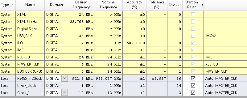
Anyways, back to EMI now. Will play with some Digital IO slew rates today. I not the IMO has a fundamental frequency of 3MHz and internal PLL mixes up to the 24MHz with around +/- 1% accuracy. I wonder if there is a component of the mixing product of the 3MHz and 24MHz producing a third harmonic. ie. 3 x 27 MHz = 81 MHz?
- Mark as New
- Bookmark
- Subscribe
- Mute
- Subscribe to RSS Feed
- Permalink
- Report Inappropriate Content
Staying off-topic, it is spelled "Yacht" and there is no "pacht", or are you talking about "pot"?
EMI: CapSense oscillations? the caps are comparably small.
How are unused pins configured? Hi-Z? Try (will cost power) to set them resistive to ground.
Bob
- Mark as New
- Bookmark
- Subscribe
- Mute
- Subscribe to RSS Feed
- Permalink
- Report Inappropriate Content
arhh, my spelling is ar tro shus. Must be the pot.