


- Mark as New
- Bookmark
- Subscribe
- Mute
- Subscribe to RSS Feed
- Permalink
- Report Inappropriate Content
Hi
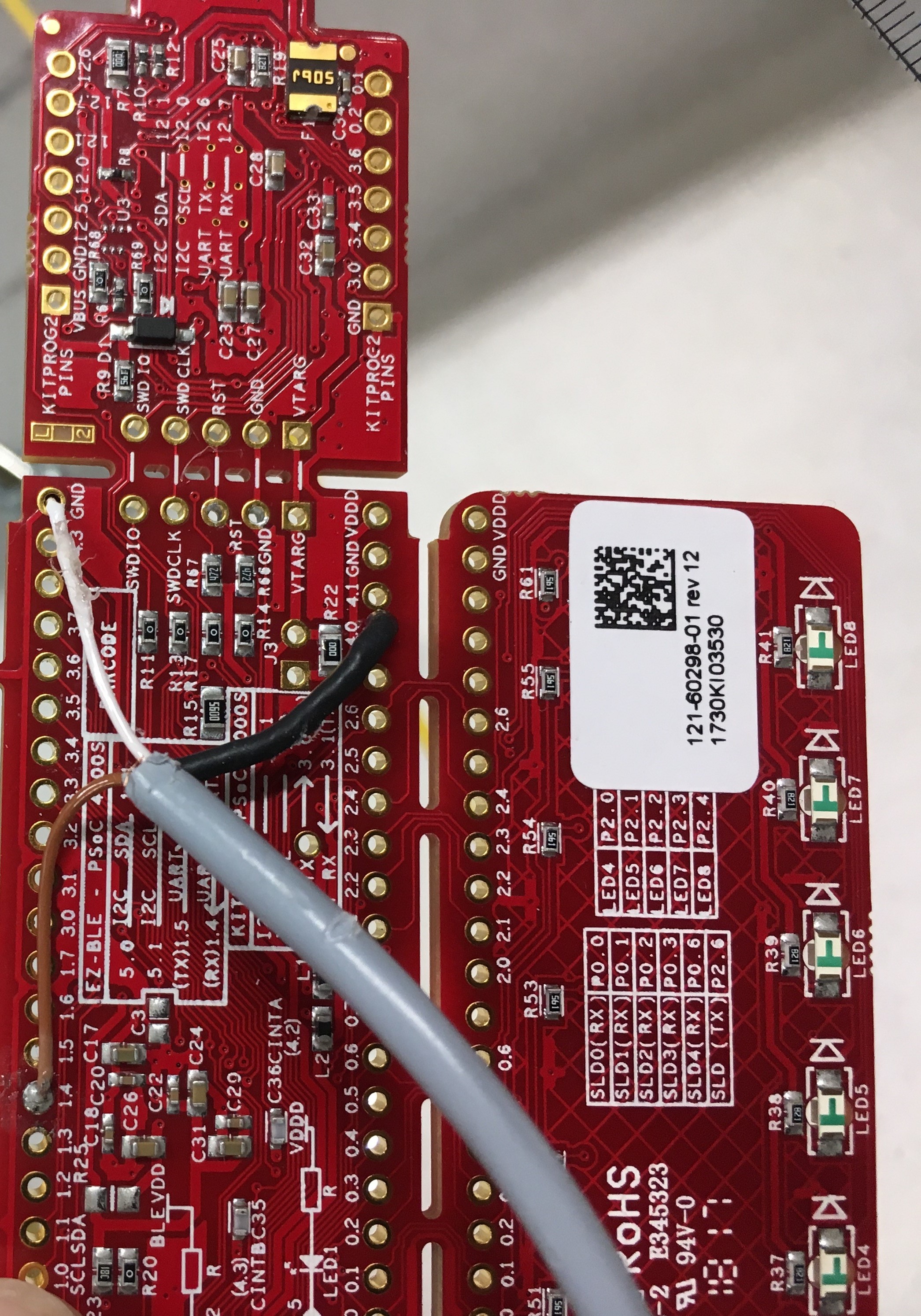
I have connected the sensor we designed with a sensing loop and the ground loop.
The sensor PCB has a shield at the bottom so that it should not sense any thing from bottom.
But in our case the sensor is sensing at the bottom. I have attached the design pic in the mail.
do you have any suggestions that i have to change the pin connections.
Any suggestions for the sensor cord that we have to use for better sensing.
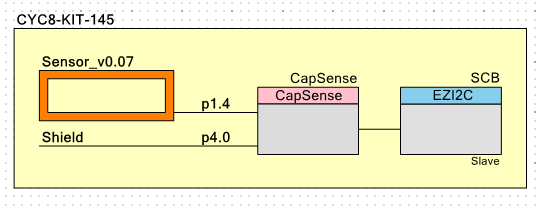
pin connections:
sense loop to pin 1.4
shield to pin 4.0
ground loop to GND.
and sensor cord i used is PURtronic-D 3*0.14mm
I have attaches the snsorcord connections pics also to the mail.In that connections I have a doubt that the shield of the sensor cord is connected to the GND or pin 4.0 on the kit. The small inner wires in sensor cord is connected to GND pin and the pin 1.4.
is the connection rite or wrong.
Solved! Go to Solution.
- Mark as New
- Bookmark
- Subscribe
- Mute
- Subscribe to RSS Feed
- Permalink
- Report Inappropriate Content
Hi LaKa_4300241
While checking sensor's activity in the bottom layer, please make sure that you are not touching the wires connecting the sensor to the kit. Cypress recommends using a 7-mil thick PCB trace for connecting CapSense traces. The thicker the wire, the more sensitive the wire becomes. Hence it is possible that the wire is causing the increased signal and not the proximity sensor.
Also please share a picture of the sensor also so that we can understand the setup better.
"I have a doubt that the shield of the sensor cord is connected to the GND or pin 4.0 on the kit. "
Can you please elaborate this point? You can probe the shield pin to see if the shield hatch is getting charged and discharged. Please share a screenshot of the oscilloscope output.
Thanks and regards
Hari