

- Mark as New
- Bookmark
- Subscribe
- Mute
- Subscribe to RSS Feed
- Permalink
- Report Inappropriate Content
Hi,
We have a problem with starting a speed BLDC motor for fan application by using Eval-M1-IM231 + EVAL-M1-101T combinations. We used MCEWizard for configuration parameters, then used the MCEDesigner to load the parameters and test. Unfortunatelly, the motor did not start properly. Instead it vibrated with very slow rotations (1rpm)
Our motor is a very high speed motor with a target speed of 80000rpm. It has low inertia load (relatively small fan blades) The motor spec is:
100W, 6 pole, Lq,Ld=3mH, Ke=1.29V/krpm, Stator resistance=21 Ohm.
We used 20kHz PWM speed.
Would you be able help? any suggestions?
Thanks
teo
Solved! Go to Solution.
- Labels:
-
ispn:17341:1:0
-
ispn:21721:1:0
-
l1:314:1:0
- Mark as New
- Bookmark
- Subscribe
- Mute
- Subscribe to RSS Feed
- Permalink
- Report Inappropriate Content
Hi @tolga,
Thanks for sharing the .mc2 file.
We have found a few parameters which you could try modifying:
Ques60 - Flux Estimator Time Constant Which is should be 4-5 times of motor time constant ( L/R) from your motor specification it is 1.4mSec ( Assuming Line to line Inductance = 6mH )Could you please try changing this value?
Ques 61 - Speed Feedback Filter Time Constant = (1/ Speed Filter Bandwidth in rad/s). Please change this value according to your Speed loop bandwidth.
Ques 14- Low-Speed Current Limit - We have observed you have set a very low starting current of 10% of Rated Please try increasing the starting current to 30-50% and observe the motor.
Could you please try running in the Open-loop by doing the following changes and share the result with us:
Ques 15- Initial Angle Sensing - Disable as this works better for salient Rotor where Ld and Lq are different
Ques 11 - Open Loop Speed Ramp Rate - Please try adjusting this value from 50 RPM/S to 1000 RPM/S and observe the motor behavior.
Ques 12 - Parking Time - Could you please try to enable parking if the starting rotor position is not essential as the motor will initially align to a certain position and starts.
Ques 13- Low-Speed Threshold Limit - This is the speed from which the motor is in a closed-loop, So you could try reducing this from 10000 RPM to some lower RPM.
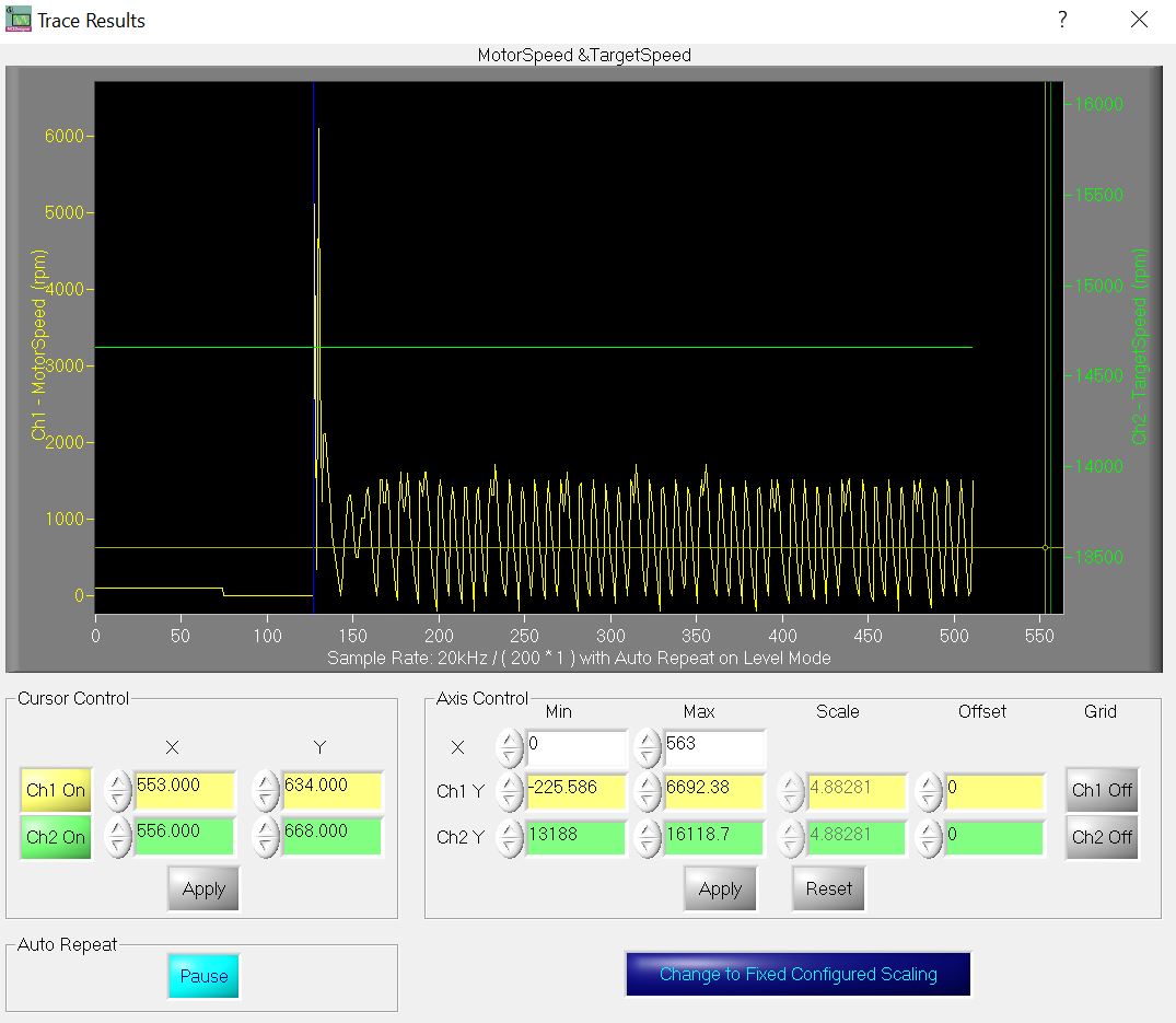
We observed that there appears to be a mismatch between the wizard parameters and the registers info. For example, the target speed is set to 80.000rpm but the target speed in start_motor tasks shows 14653 rpm. This is also what is shown in the trace graphs. I attached the Motor speed and the target speed graph for your info. (the jpeg file) Why is it different?
Could you please confirm if the target speed and reference speed are the same in your MCE Designer? ( Ref Image )

Could you please try changing these parameters and find out if it solves your issue?
Thanks,
Krupashankar
- Mark as New
- Bookmark
- Subscribe
- Mute
- Subscribe to RSS Feed
- Permalink
- Report Inappropriate Content
Hi @tolga,
Thanks! for posting in the Infineon community.
the motor did not start properly. Instead, it vibrated with very slow rotations (1rpm)
Could you please tell us if the motor continues to run at a very low speed or you are getting any errors?
This may be due to Flux PLL being out-of-control. This could happen if the speed ramp rate is high. Could you please try reducing the parameters Speed Ramp rate ( Question 10) Open-loop Speed Ramp rate ( Question 11)If you are starting with an open loop? There could be other configuration issues( Eg Improper current sensing parameters etc) for identifying those could you please share MCE Wizard Configuration file (.mc2)
For this speed of the motor, we assume you will be using sensor-less control, In the case of sensor-less control the estimation of the precise angle depends on correct measurement of Ld, Lq, B-emf Constant, and Stator resistance. Please make sure these parameters are measured correctly.
Could you please share the MCE Wizard Configuration ( .mc2) file this will help us in understanding the configured parameters and help us to determine the cause of this issue?
Thanks,
Krupashankar

- Mark as New
- Bookmark
- Subscribe
- Mute
- Subscribe to RSS Feed
- Permalink
- Report Inappropriate Content
Hi Krupashankar,
Thanks for your speedy response.
Yes, the motor stops after 8-10 secs 1rpm running/vibrating then we get a "Rotor Lock" failure
We tried playing with several parameters including speed ramp rate. We even tried 1rpm speed ramp rate. We observed no change in the motor behaviour. We also changed the Regulator parameters (Q58-63) by factor of up to 10 (both increase and decrease). Again, no change in behaviour. We only observed a behaviour change when we changed the motor control mode from speed mode to current and voltage modes. In those modes, motor did not rotate at all, instead it made noises.
We measured the motor parameters according to your "Infineon-How-to-Measure-Motor-Parameters-ApplicationPresentation-v01_00-EN" document.
I attached the .mc2 and the parameter file generated by the wizard
We observed that there appears to be a mismatch between the wizard parameters and the reristers info. For example the target speed is set to 80.000rpm but the target speed in start_motor tasks shows 14653 rpm. This is also what is shown in the trace graphs. I attached the Motor speed and the target speed graph for your info. (the jpeg file) Why is it different?
Thanks
Tolga
- Mark as New
- Bookmark
- Subscribe
- Mute
- Subscribe to RSS Feed
- Permalink
- Report Inappropriate Content
Hi @tolga,
Thanks for sharing the .mc2 file.
We have found a few parameters which you could try modifying:
Ques60 - Flux Estimator Time Constant Which is should be 4-5 times of motor time constant ( L/R) from your motor specification it is 1.4mSec ( Assuming Line to line Inductance = 6mH )Could you please try changing this value?
Ques 61 - Speed Feedback Filter Time Constant = (1/ Speed Filter Bandwidth in rad/s). Please change this value according to your Speed loop bandwidth.
Ques 14- Low-Speed Current Limit - We have observed you have set a very low starting current of 10% of Rated Please try increasing the starting current to 30-50% and observe the motor.
Could you please try running in the Open-loop by doing the following changes and share the result with us:
Ques 15- Initial Angle Sensing - Disable as this works better for salient Rotor where Ld and Lq are different
Ques 11 - Open Loop Speed Ramp Rate - Please try adjusting this value from 50 RPM/S to 1000 RPM/S and observe the motor behavior.
Ques 12 - Parking Time - Could you please try to enable parking if the starting rotor position is not essential as the motor will initially align to a certain position and starts.
Ques 13- Low-Speed Threshold Limit - This is the speed from which the motor is in a closed-loop, So you could try reducing this from 10000 RPM to some lower RPM.
We observed that there appears to be a mismatch between the wizard parameters and the registers info. For example, the target speed is set to 80.000rpm but the target speed in start_motor tasks shows 14653 rpm. This is also what is shown in the trace graphs. I attached the Motor speed and the target speed graph for your info. (the jpeg file) Why is it different?
Could you please confirm if the target speed and reference speed are the same in your MCE Designer? ( Ref Image )
Could you please try changing these parameters and find out if it solves your issue?
Thanks,
Krupashankar
- Mark as New
- Bookmark
- Subscribe
- Mute
- Subscribe to RSS Feed
- Permalink
- Report Inappropriate Content
Hi Krupashankar,
Thanks for the recommendations. We tried them all but we did not observe any change in the motor behaviour. The target and the reference speeds still appear to be incorrect (see attached in the zip file) Could that be to do with the .irc file? We use "IMC101T_V1.03.03.irc" file for Eval-M1-IM231 + EVAL-M1-101T setup. Is it the correct file?
There was an error in the motor pole number. It is actually a 4 pole motor, not a 6 pole one. We corrected it but again, no change in the motor behaviour. We also slightly changed the motor inductance to 3.5mH.
I attached the recent .mc2 files (in the zip file) with your suggestions implemented.
Unfortnatelly, the wizard gave an errror when we tried 1.4msec flux estimeter time constant. Minimum it accepts is 1.6msec. Also minimum speed filter time constant is 0.06ms
What could we try next?
Thanks
Tolga
- Mark as New
- Bookmark
- Subscribe
- Mute
- Subscribe to RSS Feed
- Permalink
- Report Inappropriate Content
Hi @tolga,
Thanks! for the feedback and details.
Could you please share the motor datasheet?
Please make sure you have measured and entered all the motor parameters correctly as per measurements and motor datasheet.
We could see that Ques 4 -Motor Stator Resistance Rs is 21ohm, Is it line to line resistance or per phase resistance. Please make sure this 0.5 of Line-Line Resistance.
We could find that motor rated amps is 0.5 A could you please confirm it with the motor datasheet?
Could you please make sure if the input is in the below range:

After entering the correct motor parameters, Could you please try running FOC in Current control mode as mentioned in application note AN2020-12: AN2020-12 Driving high inertia loads with iMOTION™2.0 and share the result with us?
The target and the reference speeds still appear to be incorrect (see attached in the zip file) Could that be to do with the .irc file? We use "IMC101T_V1.03.03.irc" file for Eval-M1-IM231 + EVAL-M1-101T setup. Is it the correct file?
Target speed and reference speed use the same register so modify target speed and reference speed to the same value. Yes, you can use IMC101T_V1.03.03.irc Please make sure to update the correct register map file.
Thanks,
Krupashankar
- Mark as New
- Bookmark
- Subscribe
- Mute
- Subscribe to RSS Feed
- Permalink
- Report Inappropriate Content
Hi Krupashankar,
The motor is from a Chinese company. There is very little information on the datasheet and some of them are wrong. So, we decided to measure the motor parameters ourselfs.
The datasheet states the motor is a 100W one but not mentioning the rated current. We think for a 100W motor, it should be 0.4-0.5A region. We used 0.5A for the wizard.
We measured line to line resistance as 42 Ohm. So the stator resistance is 21 Ohms.
We measured line to line inductance as 7mH, so Lq should be 3.5mH. We were unable to measure Ld, but we think it is same as Lq. (We asked to Chinese manufacturer)
We tried the current mode. The rotor rotated at around a few 100rpm when IqrefExt= 0.02-0.01 Arms but it wasn't runnning reliably. It was shaking possibly due to accelerating and deaccelerating.
We also tried open loop but that did not work. We got a gate kill error for Vq_ext=100V. Then we tried for V_ext=15V. It did not cause gate kill but the motor was getting hott and not spinning. (30W power drawn from mains)
So, any further recommendations?
Btw, we also have an "EVAL-IMM101T-046TOBO1" EV-Kit. It uses the same Imotion engine as far as we understand.
Thanks
- Mark as New
- Bookmark
- Subscribe
- Mute
- Subscribe to RSS Feed
- Permalink
- Report Inappropriate Content
Hi @tolga,
Could you please share the below details:
- How did you measure the motor b-emf constant
- What is the input voltage of the power board
-
The datasheet states the motor is a 100W one but not mentioning the rated current. We think for a 100W motor, it should be 0.4-0.5A region. We used 0.5A for the wizard.
What is the motor operating voltage range? Current depends on motor rated voltage and power.
- What is the DC bus voltage in power board?
-
We measured line to line inductance as 7mH, so Lq should be 3.5mH. We were unable to measure Ld, but we think it is same as Lq. (We asked to Chinese manufacturer)
What is the LCR frequency you have used for measuring Rs, Ld, and Lq ( Lq = Lmax/2 and Ld = LMin/2 ) the inductance will vary as you rotate the motor shaft will help in determining Ld and Lq?
These details will help us to figure out if there is any other potential issue
The motor is from a Chinese company. There is very little information on the datasheet and some of them are wrong. So, we decided to measure the motor parameters ourselfs.
Motor parameters are very essential in the case of sensorless control, these parameters used in MCE to determine the rotor angle for reliable closed-loop operation.
Btw, we also have an "EVAL-IMM101T-046TOBO1" EV-Kit. It uses the same Imotion engine as far as we understand.
Yes, EVAL-IMM101T-046 uses the same iMotion engine (MCE).
Thanks,
Krupashankar
- Mark as New
- Bookmark
- Subscribe
- Mute
- Subscribe to RSS Feed
- Permalink
- Report Inappropriate Content
Hi Krupashankar,
We rotated the motor with a cordless drill to measure peak to peak voltage and the frequency on one of windings. Then we used "Infineon-How-to-Measure-Motor-Parameters-ApplicationPresentation-v01_00-EN" formula to calculate b-emf constant. However we are not sure about Npolepairs parameter. We have a 4 pole motor. Does that mean Npolepair=2 ??? (If we use 2, Ke would be half of the value and we get error messages from the wizard)
The DC bus voltage is 325V
We used 1kHz measurement frequecny on the LCR meter to measure Lq. We used a multimeter to measure Rs. Lmax and Lmin were measured as 7mH and 6.76mH respectively by tweaking the rotor position. Does that mean Ld=6.76/2=3.38mH?
We will enter Ld as 3.38mH and retry.
Btw we recently acquired another EV kit set which is EVAL-M7-HVMOS-INV+EVALM7D111TTOBO1. This kit is based on a single shunt as default. When we tried this kit and ran VF diagnostics with Vd_ext=10V and target speed=1000, we managed rotating the rotor at several 100s rpm. But, the motor reached to 10x lower than the target speed parameter...
Btw, it is worth pursuing the procedure on page 14 of this document? : https://eu.mouser.com/datasheet/2/196/Infineon_UG2020_16_Ref_Hairdryer_C101_6ED_UserManu-1947443.pdf
Thanks
Tolga
- Mark as New
- Bookmark
- Subscribe
- Mute
- Subscribe to RSS Feed
- Permalink
- Report Inappropriate Content
Hi @tolga
We have a 4 pole motor. Does that mean Npolepair=2 ???
Yes, pole pair = number of poles /2;
In your case of 4 poles, number of pole pairs is 2.
The DC bus voltage is 325V
Could you please confirm if the motor operating voltage is in this range?
We used 1kHz measurement frequency on the LCR meter to measure Rs and Lq. Lmax and Lmin were measured as 7mH and 6.76mH respectively by tweaking the rotor position. Does that mean Ld=6.76/2=3.38mH?
We will enter Ld as 3.38mH and retry.
Yes, you could try entering Ld as 3.38mH and Lq as 3.5mH
Btw we recently acquired another EV kit set which is EVAL-M7-HVMOS-INV+EVALM7D111TTOBO1. This kit is based on a single shunt as default. When we tried this kit and ran VF diagnostics with Vd_ext=10V and target speed=1000, we managed rotating the rotor at several 100s rpm. But, the motor reached to 10x lower than the target speed parameter...
Both the Eval board uses the same iMotion 2.0 and motor parameters and power board parameters have to be configured correctly could you please share the .mc2 file for the same. Could you please let us know the motor operating voltage range?
Thanks,
Krupashankar
- Mark as New
- Bookmark
- Subscribe
- Mute
- Subscribe to RSS Feed
- Permalink
- Report Inappropriate Content
Hi Krupashankar,
When I use pole pair as 2 as you suggested I get Ke=0.88. When I enter Ke as 0.88 I get "Motor 1 Volt scl value out of range" error. So what should I do?
Yes the motor is operating in that range. (325V)
I tried Ld as 3.38mH. No affect.
Btw, maybe more importantly, it seems I can't change the PLL frequecny. I set motor 1 pwm frequecny as 25kHz in the wizard but, I measured it as 15kHz with an oscilloscope while running VF Diagnostic. Why is that? Could that be a bug?
Thanks
Tolga
- Mark as New
- Bookmark
- Subscribe
- Mute
- Subscribe to RSS Feed
- Permalink
- Report Inappropriate Content
- Mark as New
- Bookmark
- Subscribe
- Mute
- Subscribe to RSS Feed
- Permalink
- Report Inappropriate Content

Also, why am I reading a much higher voltage value? (see above) I've just measured it as 321Vdc.... Something is wrong..
Thanks Tolga
- Mark as New
- Bookmark
- Subscribe
- Mute
- Subscribe to RSS Feed
- Permalink
- Report Inappropriate Content
Hi again,
I switched to EVAL-IMM101T-046 board. Now the VdcRaw and Vdcfilt show the correct values on this EV kit. But, I still get 15kHz PWM freq although it was set to 25kHz in the wizard???
Tolga
- Mark as New
- Bookmark
- Subscribe
- Mute
- Subscribe to RSS Feed
- Permalink
- Report Inappropriate Content

It seems this is the reason why the PWM freq has not been changed. (See above) How can I override? Are there other parameters which might not have been changed for similar reasons?
Thanks
Tolga
- Mark as New
- Bookmark
- Subscribe
- Mute
- Subscribe to RSS Feed
- Permalink
- Report Inappropriate Content
Flxtau not updated too. Potentially all the static registers not updated.

- Mark as New
- Bookmark
- Subscribe
- Mute
- Subscribe to RSS Feed
- Permalink
- Report Inappropriate Content
Hi @tolga,
Yes, The above problem arises when the register is not updated.
You can click on configure motor as shown in below picture red circle

Once you click configure motor all the registers will be refreshed and updated as in the yellow box.
You can also try clicking update parameter value of each register and for further information please refer to MCEDesigner Application Guide ( attached)
Please let us if the problem still persists and We will work to resolve this issue
Thanks,
Krupashankar
- Mark as New
- Bookmark
- Subscribe
- Mute
- Subscribe to RSS Feed
- Permalink
- Report Inappropriate Content
Hi Krupashankar,
No configure motor did not work. Hovewer, I managed to update the static parameters by using tools->Programming->parameters rather than Files->import drive parameters.
Now I am triying to run the motor in current mode. It fails to start. It seems it is to do with the flux estimator. What should I do next? See below:

Tolga
- Mark as New
- Bookmark
- Subscribe
- Mute
- Subscribe to RSS Feed
- Permalink
- Report Inappropriate Content
Hi Krupashankar,
I've changing the flux estimater time constant. I am getting "flux out of control" message when I try to to the motor in current mode. The flux estimater time constant is currently set to 1.7ms. Is there any way of calculating it? Any formula?
Also, what other parameters we should tweak?
Btw, this is the motor spec:
Number of poles: 4
Configuration: 3 Phase
The target motor speed: 120000 rpm
Motor Power: 100W
Motor current: 0.44A rms (This is calculated, not measured)
Motor DC voltage: 325V
Stator resistance= 21 Ohm (42 Ohm line to line)
Lq= 3mH (7mH line to line)
Ld= 3.38mH (6.76mH line to line)
Ke=0.88 V/krpm
Thanks
Tolga
- Mark as New
- Bookmark
- Subscribe
- Mute
- Subscribe to RSS Feed
- Permalink
- Report Inappropriate Content
Hi Krupashankar,
Now I am getting interesting Iu and Iv current waveforms. The motor running smoothly in open loop mode. But the current waveforms distorted in a way as if they are folded from the middle point of the sinewave signals. Btw, low noise phase shift current sensing is enabled. see below

Tolga
- Mark as New
- Bookmark
- Subscribe
- Mute
- Subscribe to RSS Feed
- Permalink
- Report Inappropriate Content
Hi @tolga,
Could you please contact the motor manufacturer to find the rated voltage of the motor?
Motor-rated voltage is a very essential parameter for the operation of the motor.
Thanks,
Krupashankar