


- Mark as New
- Bookmark
- Subscribe
- Mute
- Subscribe to RSS Feed
- Permalink
- Report Inappropriate Content
Hi,
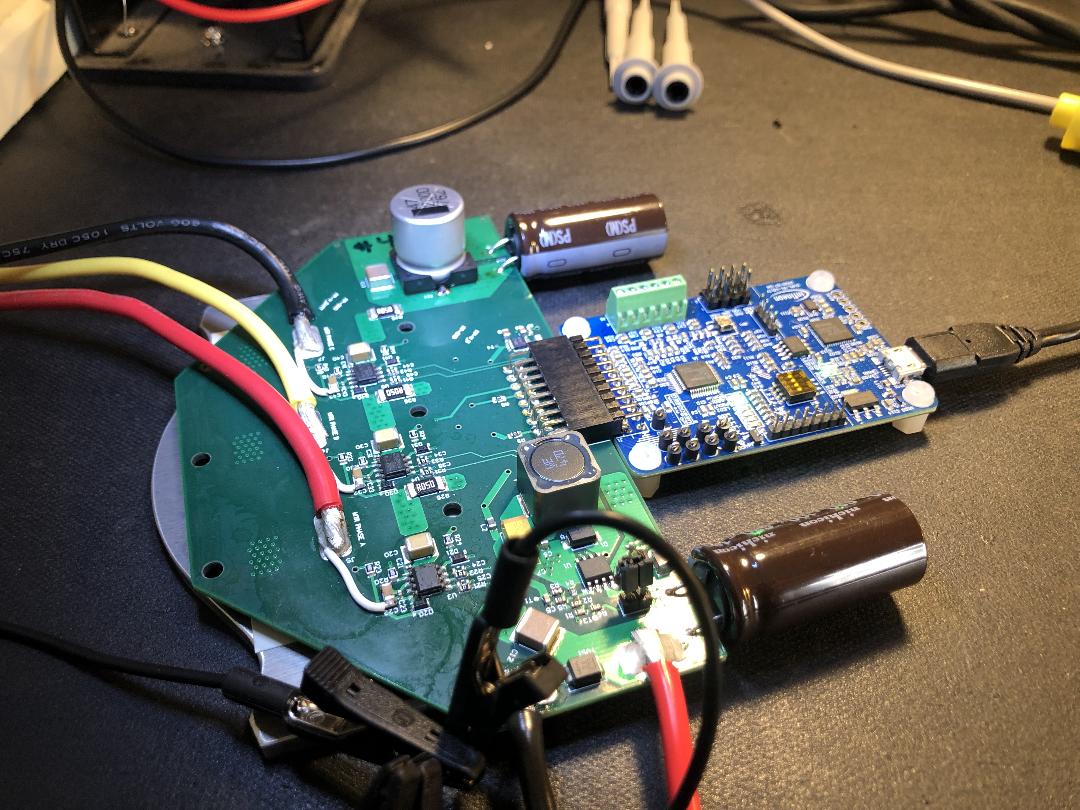
I am working with the Infineon IMC101TF048XUMA1 motor controller for controlling a PMSM motor for an underwater thruster. All is up and running on a custom designed drive board attached to a EVAL-M1-101TFTOBO1 development board as you can see in the photo below. Also am using 6 of Infineon MOSFETs, IPTC019N10NM5 per board.
In our existing configuration, the motor operates smoothly up to around 1100 or 1200 rpm, unloaded in air. However when commanding the motor up to a slightly higher speed, it is getting a Over Current fault (GK). It runs fine at all speeds below this speed while increasing and decreasing speeds in this range. It also works fine in both directions. We have setup all motor parameters to match. Adjusting the other parameters has not helped to this point. I have turned up the guard band to 5 microseconds which helped us reach a slightly higher speed, but we still get the faults when running above 1200 rpm.
I have attached a schematic as well as the most recent setup files for the IMC101TF. (Unfortunately, this forum only allows certain doc forms, so I converted to PDFs for some)
Power supply rails (battery at 70V, DC and Vgs at 12V and linear regulator at 5V for the motor controller) remain stable during operation.
Does someone have any idea what would cause issues when a certain speed is reached with this setup?
Solved! Go to Solution.
- Mark as New
- Bookmark
- Subscribe
- Mute
- Subscribe to RSS Feed
- Permalink
- Report Inappropriate Content
Hi @aneedles,
We would recommend following this document: How to Measure Motor Parameters
Please make sure Ques 4 - Motor Stator Resistance and Ques 7 Motor Back EMF Constant (Ke) are measured and entered as per the document.
Thanks,
Krupashankar
- Mark as New
- Bookmark
- Subscribe
- Mute
- Subscribe to RSS Feed
- Permalink
- Report Inappropriate Content
Hi @aneedles,
Thanks for posting in the Infineon Community.
We could see that you have set Motor Rated AMPS(Ques 2) to 82.73A but the motor maximum current, Overcurrent Trip Level for Internal Gatekill Comparator ( Ques -93) is set to 40A lower compared to the rated current.
Could you please let us know if you have made any changes to R9 and R10 resistors? If not, based on your shunt resistor of 50mOhm Motor1 Current Input scaling ( Ques 83 ) has to be changed to 41.665mV/A.
Please try increasing Overcurrent Trip Level for Internal Gatekill Comparator ( Ques -93) to higher values if the motor supports higher current to avoid overcurrent fault.
Thanks,
Krupashankar
- Mark as New
- Bookmark
- Subscribe
- Mute
- Subscribe to RSS Feed
- Permalink
- Report Inappropriate Content
Hi Krupashankar,
Thanks for your response, and good catch on the scaling. I had forgotten that I had made this change in order to get more current range. The resistor used for Rs for each of the three phases is now 5mOhms rather than 50mOhms. So I think the Motor1 Current Input scaling ( Ques 83 ) is correct as 4.16665mV/A.
The Overcurrent Trip Level for Internal Gatekill Comparator ( Ques -93) is purposely set low because we are intermittently getting damage to the hardware when these faults occur, so a lower value still allows operation, but hopefully also better protection when the current does spike high. Of course, when we run in the final application (with propeller in water rather than in air) this will need to be raised to a reasonable limit.
Any other ideas on what could be going unstable and causing sudden high currents, just at higher speeds?
Thanks,
Aaron
- Mark as New
- Bookmark
- Subscribe
- Mute
- Subscribe to RSS Feed
- Permalink
- Report Inappropriate Content
Hi @aneedles,
Could you please share with us the current waveform which will help us to understand the rise of the current?
Have you tried enabling field weakening at higher speeds and observed the behavior of the motor?
Thanks,
Krupashankar
- Mark as New
- Bookmark
- Subscribe
- Mute
- Subscribe to RSS Feed
- Permalink
- Report Inappropriate Content
Hi Krupashankar,
Here are current waveforms at the time of fault. I have also added 10% field weakening current limit, but see no affect on operation or the faulting behavior.


Current at motor startup, for reference:

Flux waveforms on fault:

- Mark as New
- Bookmark
- Subscribe
- Mute
- Subscribe to RSS Feed
- Permalink
- Report Inappropriate Content
Hi @aneedles,
Thanks for sharing the speed and current waveform.
This can happen if the motor-rated RPM is less than the motor maximum RPM set in MCE Wizard.
From your back-emf constant we could find that your rated RPM of the motor will be less than 1300 RPM when you try to run the motor above this speed it may result in higher current consumption and speed may oscillate due to your PI controller settings.
Thanks,
Krupashankar
- Mark as New
- Bookmark
- Subscribe
- Mute
- Subscribe to RSS Feed
- Permalink
- Report Inappropriate Content
Krupashankar,
Can you please share your calculation where you derived rated RPM for our motor being less than 1300rpm?
Our motor's V/krpm (Peak line-line EMF) is 41.473 which at 1300rpm would give 53.91Vpeak back EMF. Our DC bus is provided by a battery at 70 volts and so should have the ability to provide current to drive the motor to this speed, especially unloaded. I am not understanding where there would be a problem, so would appreciate more explanation.
Thanks,
Aaron
- Mark as New
- Bookmark
- Subscribe
- Mute
- Subscribe to RSS Feed
- Permalink
- Report Inappropriate Content
Hi @aneedles,
Based on your .mc2 configuration
Ques 7 : Motor Back EMF Constant(Ke) - 29.326 Vrms/ KRPM
Ques 2: Motor Rated Amps - 82.73A
Ques 4 : Motor Stator Resistance - 0.069 ohm/phase
For RPM of 1300 RMS voltage will be 29.326( Vrms/ KRPM) *1.3( KRPM) = 38.123 Vrms
Peak Voltage = 1.414* 38.123 = 53.905 V
IR drop at rated current = 82.73A * 0.138 ( Line to line resistance = 2 * 0.069(per phase resistance)) = 11.41 V
line voltage = 53.905 V + 11.41 V = 65.321 V
This is very close to DC bus voltage and here we have not considered losses. Please correct me If I am wrong and I hope that battery DC bus voltage is constant( 70V) at the rated speed.
Thanks,
Krupashankar
- Mark as New
- Bookmark
- Subscribe
- Mute
- Subscribe to RSS Feed
- Permalink
- Report Inappropriate Content
Hi Krupashankar,
Thanks for writing out the details.
Our datasheet does not include a rated torque value, but does shown an application example that is similar to the conditions that we will run with. The example is on the attached datasheet as the first PERFORMANCE EXAMPLE with 1200rpm and current of 22.257A-peak and 15.511A-rms.
So the actual current we will be running with looks to be considerably lower in the range of 25A peak.
Furthermore, I am running the motor unloaded in air, and I am experiencing these issues I have described while using less than 100W of power from the battery. We should not be anywhere close to the DC bus voltage limit.
- Mark as New
- Bookmark
- Subscribe
- Mute
- Subscribe to RSS Feed
- Permalink
- Report Inappropriate Content
Hi @aneedles,
We would recommend following this document: How to Measure Motor Parameters
Please make sure Ques 4 - Motor Stator Resistance and Ques 7 Motor Back EMF Constant (Ke) are measured and entered as per the document.
Thanks,
Krupashankar
- Mark as New
- Bookmark
- Subscribe
- Mute
- Subscribe to RSS Feed
- Permalink
- Report Inappropriate Content
A cautionary note to others - infineon specifies the Back EMF constant in MCEWizard in ln-rms configuration which is different that the representation in many datasheets. We missed this nuance and had our Back EMF constant set incorrectly which lead to the behavior we indicated above. I suggest that customers look at the description in MCEWizard very closely to ensure you have the constant specified correctly.
- Mark as New
- Bookmark
- Subscribe
- Mute
- Subscribe to RSS Feed
- Permalink
- Report Inappropriate Content
Hi, @aneedles
I'm having the same problem as you.
I am using the Single Shunt method and I am a BLDC motor.
However, RPM fails to enter high-speed RPM and continues to drop.
After measuring the Backemf accurately again, did the problem improve again?
And could you tell me how to measure the back emf accurately? I can't understand even if I read that document.
I need your help.
Please answer me.