


- Mark as New
- Bookmark
- Subscribe
- Mute
- Subscribe to RSS Feed
- Permalink
- Report Inappropriate Content
Hello,
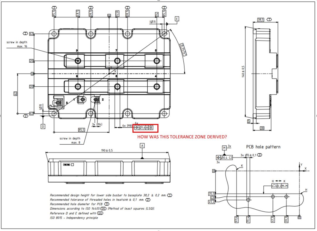
I was wondering how the geometric tolerance for the M8 mounting holes on your IGBT drawing in the technical specifications for the FZ1800R45HL4_S7 IHM-B module was derived?
I am trying to make an assembly with this part and the tolerance zone of 1.6 mm called out in your drawing from DATUMS A, D, and seems puzzling to me and fairly large. Could you please provide some documentation on how this tolerance in the spec drawing was derived or the reasoning behind it from the mechanical dimensions of the bolt holes. I have attached an image of what I am talking about.
Thank you
Solved! Go to Solution.
- Labels:
-
ispn:31402:1:0
-
l1:144:1:0
-
l2:219:1:0
-
l3:238:1:0
- Mark as New
- Bookmark
- Subscribe
- Mute
- Subscribe to RSS Feed
- Permalink
- Report Inappropriate Content
Hello @willpease
The Cpk value 1.5 is not measurable it is a consideration for the calculation of tolerance.
In process improvement efforts, the process capability index or process capability ratio is a statistical measure of process capability: the ability of a process to produce output within specification limits. The concept of process capability only holds meaning for processes that are in a state of statistical control. Process capability indices measure how much "natural variation" a process experiences relative to its specification limits and allows different processes to be compared with respect to how well an organization controls them.
Thanks
Guru
- Mark as New
- Bookmark
- Subscribe
- Mute
- Subscribe to RSS Feed
- Permalink
- Report Inappropriate Content
Hello @willpease
Thanks for posting your questing in Infineon community.
A statistically representative sample was measured and the tolerance was designed with a Cpk greater than 1.5.
Please let me know if you need any help
Thanks
Guru
- Mark as New
- Bookmark
- Subscribe
- Mute
- Subscribe to RSS Feed
- Permalink
- Report Inappropriate Content
Hello Guru,
Yes I can use some help. The datums D and E are the IGBT holes for the M6 screws with have a positional tolerance of +/- 0.1 mm which corresponds to a circular tolerance zone of diameter 0.283 mm. Those holes on the drawing indicate that at MMC the diameter is 7mm which is 1mm larger than the M6 fastener at MMC. So adding a 0.5mm diameter tolerance zone for the M6 fastener could move inside the 7mm hole and the .283mm tolerance zone. The mot I calculate the M8 holes could be positioned off of the M6 datum holes is 0.783 mm, which is roughly half of the tolerance zone of 1.6mm called out in the drawing. So I am wondering how the M8 holes which are manufactured and placed with respect to the datum holes D and E in the drawing can have a circular tolerance zone of diameter 1.6 mm as in the drawing. It seems really large in comparison to the tolerance of the IGBT M6 mounting holes. Is there more detailed derivation you can provide other than statistically representative sample was measured to 1.5mm? or am I missing something?
Thank you,
Will Pease
- Mark as New
- Bookmark
- Subscribe
- Mute
- Subscribe to RSS Feed
- Permalink
- Report Inappropriate Content
Hello @willpease
The Cpk value 1.5 is not measurable it is a consideration for the calculation of tolerance.
In process improvement efforts, the process capability index or process capability ratio is a statistical measure of process capability: the ability of a process to produce output within specification limits. The concept of process capability only holds meaning for processes that are in a state of statistical control. Process capability indices measure how much "natural variation" a process experiences relative to its specification limits and allows different processes to be compared with respect to how well an organization controls them.
Thanks
Guru