

Clocks Forum Discussions
 Solved
https://www.cypress.com/file/43081/download
I was going through that data sheet on the CY22800 Frequency Multipliers since and since I'm trying to transform and external 1MHz clock signal to a 12MHz signal I was going to go with the -052A variant. My question is, which of Pins 5-7 is the 12 MHz signal going to be coming out of? And what voltage level should I tie pin 3 to in order to acheive this?
Show Less


I need to generate a statement of volatility for a customer using a product that uses the CY22281. One of customer's requirements is to list the size of the flash memory. I don't see this on the datasheet. What is its approximate size?
Show LessCan CY3679 clock output be hooked up to Arduino Mega 2560 5v board on xtal 1,2 inputs at 16mhz or 3.3v clock output issue.
Also clock input to CY3679 board can handle 10mhz gpsdo input or is limited to 1.2v? Thanks
Show LessHi All,
We purchased a CY3679 clock generator eval board and am trying to output a 100 MHz clock on single ended port 15. I successfully generated the JEDEC file, but when I try to program it I get the following error.
Info: JEDEC file generation completed. Project_00.jed created.
Info: Programming started for Project_00 at 07/05/2020 14:12:40
Error: Programming operation checking, status - Error: Set I2C voltage -
I can't find any settings for I2C voltage.
Previously, I was getting a different error:
Error: Programming operation checking, status - Error: Open port - KitProg version Expecting 2.21, but found 2.18.
I found a discuss that told me to run C:\Program Files (x86)\Cypress\Programmer\Service>CyMiniProg3Service.exe /service
After doing that I now get the I2C error.
Thanks in advance for your help.
D-
Show LessHello,
Please tell me the specification of Tr/Tf (Rise/Fall) for the input signal to the "REF" pin (1 pin).
Although there is a description in the data sheet that the input frequency was 1MHz to 133MHz, I could not find any description about AC timing.
MPN: CY2308ZXI-1HT
Best Regards,
Naoaki Morimoto
Show LessWhat is the recommended method to create a .JED file for CY25100 parts?
If CyClockWizard is the only option, is it compatible with Windows 10?
When attempting to run setup.exe after downloading from https://www.cypress.com/documentation/software-and-drivers/cyclockwizard-10?source=search&keywords=cyclockwizard, a PopUpBox appears with the following text. Upon hitting the [OK] button, setup appears to exit.
CyClockWizard 1.0 requires that your computer is running at least Windows Vista 32-bit or Windows XP 32-bit SP2 or Windows Server 2003 32-bit SP1 or Windows Server 2008 32-bit or Windows 32-bit SP4 with IE 6.0.
Greg
P.S. There was a similar post stating CyClockWizard 1.0 is the tool to use. Reference: @ Re: CY25100; is possible to get a software tool to generate a file to program the part?
Show Less我們一般常見的Tj (Junction temp.) 描述是指積體電路結構能接受的最高溫度,一旦超過這個溫度IC就會損毀
大多規格都是Tj ≧ Tstg,但CYPRESS大多數卻是 Tj < Tstg ,不就表示IC在高溫儲存的時候就有機會損毀嗎?
因此,是否可以協助確認一下Cypress這樣描述的原因?
以下是ROHM半導體對Storage temperature敘述請參考:
https://www.rohm.com.cn/electronics-basics/opamps/op_what11
最大接合部温度和保存温度范围
最大接合部温度是指半导体工作的最大温度。 另外,接合是指PN接合。
芯片温度高于规定的最大接合温度时,在半导体结晶中生成多个电子孔对,芯片再不可作为元件正常工作。
因此,使用和进行热设计时,需要考虑IC消耗的功率引起的散热或环境温度。
最大接合部温度由制造工艺决定。
保存温度范围表示IC在不工作的状态,即无消耗功率的状态下保存环境的最大温度。
一般与最大接合部温度的值相同。
Hi All,
Im ICT test engineer, is there any programming tools that able to program CY25100 where the device is already attached on board?
as i found out "CY3675 ClockMaker Clock Programming Kit" needs to remove the device in order to do the programming.
preferable the programming tools to have Batch file for execution.
thank you so much!
Regards,
Jan
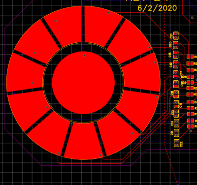
Show LessHi,
we are using a capacitive touch sensor for our application.
The design is attached below

The capacitive touch sensor has a 2.5 mm thick ABS sheet above the touch sensor.
Could you please suggest any capacitive touch sensor IC's ?
The dimensions of the design are
- the diameter of inner circle ( button) is 16mm
- The spacing between capacitive pads are 0.9 mm
- length of the pads 9.27mm
- area of each pad is 70.84 mm2
Thank-you
Warm Regards
Harini Krishna
Show LessHello
I wrote data in I2C using PSOC in CY29411, but no signal was output from either CLK_P or CLK_N.Please refer to the attachment for details including questions.
Q1) Please tell me why there is no clock out from CLK_P and CLK_N?
Q2) When the information of only the setting written in the JEDEC File is written to CY29411 by PSOC I2C, is the CLK output automatically started? Or is there any other settings to start CLKs?
Best Regards
Arai
Show Less