


- Mark as New
- Bookmark
- Subscribe
- Mute
- Subscribe to RSS Feed
- Permalink
- Report Inappropriate Content
Hi
i would like to know if its possible that one capsense could be connected to two capsense inputs?
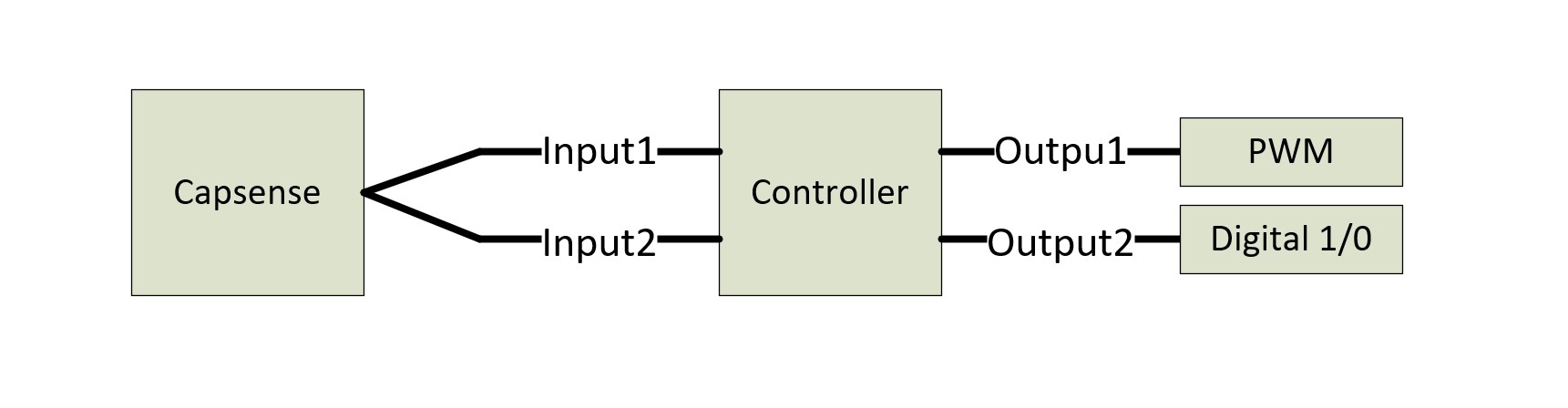
Like in the picture attached
greetings
Thomas
Solved! Go to Solution.
- Mark as New
- Bookmark
- Subscribe
- Mute
- Subscribe to RSS Feed
- Permalink
- Report Inappropriate Content
Hi @ThomasE1 ,
As you mentioned, in your Product you need one output as PWM to control LED brightness and the second output as digital to say the controller DMG is active or not. So, you know right the MBR pin GPOs will only toggle the pins high/low as programmed which would act as an indicator/interrupt source to your external MCU/IC.
Next point I had, if a single CapSense button sensor should trigger two outputs at the same time, you could always go for the following:

You can merge the output of a single GPO pin.
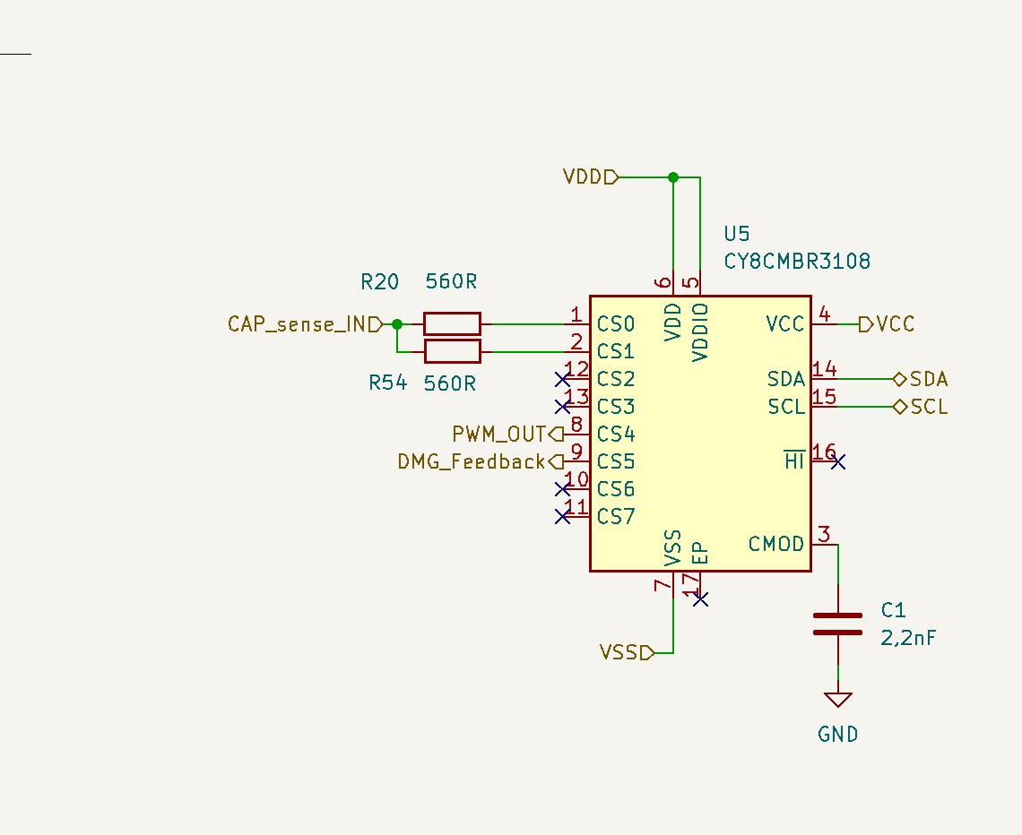
I recommend the above because, I tried to replicate the setup at my end of duplicating a single sensor. It works, but in real application it might affect the performance. As CapSense controller in the MBR kit scans the sensors one by one. The sensor will face some parasitics due the additional components during the scan. This is because the same sensor is connected to two pins via a 560ohm resistor. I would recommend having two separate buttons in that case or else go with the above scenario as per the picture attached.
Warm regards
Sobhit
- Mark as New
- Bookmark
- Subscribe
- Mute
- Subscribe to RSS Feed
- Permalink
- Report Inappropriate Content
Hi @ThomasE1 ,
May I know why you would like to gang up the CapSense pins externally for a single sensor? What is the Parasitic Capacitance of the Sensor? How is the shape and size of it?
Also please make sure you have the recommended decoupling capacitors in the schematic design for the Power supply Pins as follows:

The I2C Pins should also have respective 330Ohm Series and 4.7k/2.2k Pull-up resistances (based on the speed) on the data and clock lines.
Thanks and regards
Sobhit
- Mark as New
- Bookmark
- Subscribe
- Mute
- Subscribe to RSS Feed
- Permalink
- Report Inappropriate Content
Hi thank you for reply
I added the missing components (Capacitors and Resistors)
We are in the develop phase of a product and we dont have the designe of the Capsense finished yet.
So i do not know what parasitic capacitence it would has.
In our Product we need one outout as pwm to controll LED brightness and the second output as digital to say the controller DMG is active or not
For the reason that one Capsense Input of the Chip only controll a fixed Output pin i had the idea to connect the same sensor to two inputs. ( see attached picture)
I just want to know if thats possible.
Greetings
Thomas
- Mark as New
- Bookmark
- Subscribe
- Mute
- Subscribe to RSS Feed
- Permalink
- Report Inappropriate Content
Hi @ThomasE1 ,
As you mentioned, in your Product you need one output as PWM to control LED brightness and the second output as digital to say the controller DMG is active or not. So, you know right the MBR pin GPOs will only toggle the pins high/low as programmed which would act as an indicator/interrupt source to your external MCU/IC.
Next point I had, if a single CapSense button sensor should trigger two outputs at the same time, you could always go for the following:
You can merge the output of a single GPO pin.
I recommend the above because, I tried to replicate the setup at my end of duplicating a single sensor. It works, but in real application it might affect the performance. As CapSense controller in the MBR kit scans the sensors one by one. The sensor will face some parasitics due the additional components during the scan. This is because the same sensor is connected to two pins via a 560ohm resistor. I would recommend having two separate buttons in that case or else go with the above scenario as per the picture attached.
Warm regards
Sobhit